


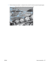
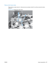
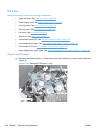
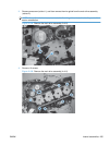
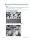

3. Remove one screw (callout 1), and then remove the wire guide from the main-drive assembly
(callout 2).
NOTE: Leave the wire harnesses connected to the wire guide and attached to the product for
easier reinstallation.
Figure 2-198 Remove the main-drive assembly (3 of 6)
1
2
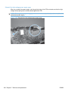
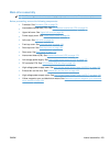
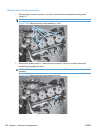
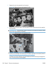
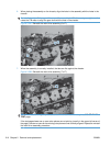
4. Remove 10 screws.
Figure 2-199 Remove the main-drive assembly (4 of 6)
1
ENWW Internal assemblies 205