


L100 Inverter
Operations
and Monitoring
4–15
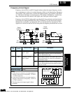
Analog Input Current/Voltage Select
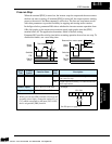
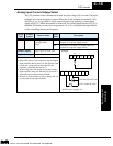
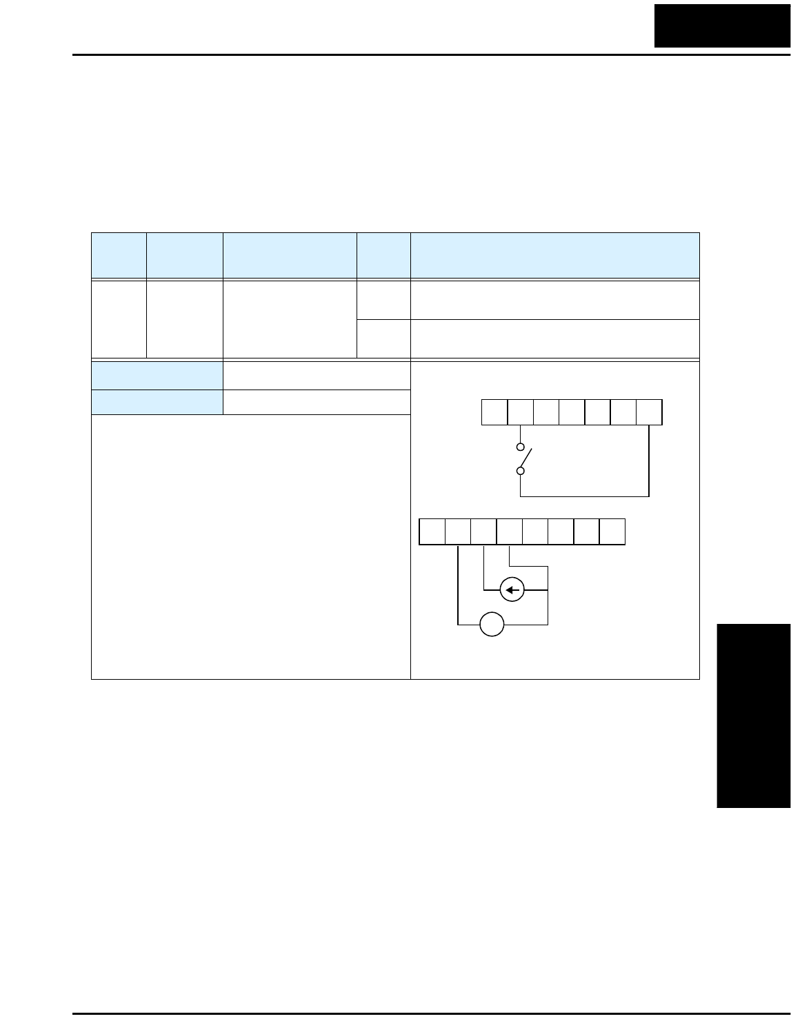
The [AT] terminal selects whether the inverter uses the voltage [O] or current [OI] input
terminals for external frequency control. When the switch between the terminals [AT]
and [P24] is on, it is possible to set the output frequency by applying a current input
signal at [OI]-[L]. When the terminal is turned off, the voltage input signal at [O]-[L] is
available. Note that you must also set parameter A1 = 01 to enable the analog terminal
set for controlling the inverter frequency.
Option
Code
Terminal
Symbol
Function Name
Input
State
Description
16 AT Analog Input
Voltage/current
Select
ON Terminal OI is enabled for current input (uses
terminal L for power supply return)
OFF Terminal O is enabled for voltage input (uses
terminal L for power supply return)
Valid for inputs:
C01, C02, C03, C04, C05
Required settings:
A01 = 01
Notes:
•
If the [AT] option is not assigned to any intelligent
input terminal, then inverter uses the algebraic sum
of both the voltage and current inputs for the
frequency command (and A01=01).
•
When using either the analog current and voltage
input terminal, make sure that the [AT] function is
allocated to an intelligent input terminal.
•
Be sure to set the frequency source setting A01=01
to select the analog input terminals.
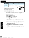
Example:
AT
1112
CM2FM
O LOIH
+ –
4-20 mA when AT= On
0-10 V when AT= Off
See I/O specs on page 4–5.
P24
123L 45
Technologies Inc.
Toll Free: voice: 1-877-539-2542 fax: 1-800-539-2542 www.mgitech.com