


“A” Group: Standard Functions
Configuring
Drive Parameters
3–10
“A” Group: Standard Functions
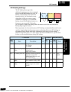
Basic Parameter Settings
These settings affect the most fundamental behavior of the inverter — the outputs to the
motor. The frequency of the inverter’s AC output determines the motor speed. You may
select from three different sources for the reference speed. During application develop-
ment you may prefer using the potentiometer, but you may switch to an external source
(control terminal setting) in the finished application, for example.
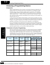
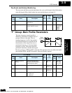
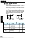
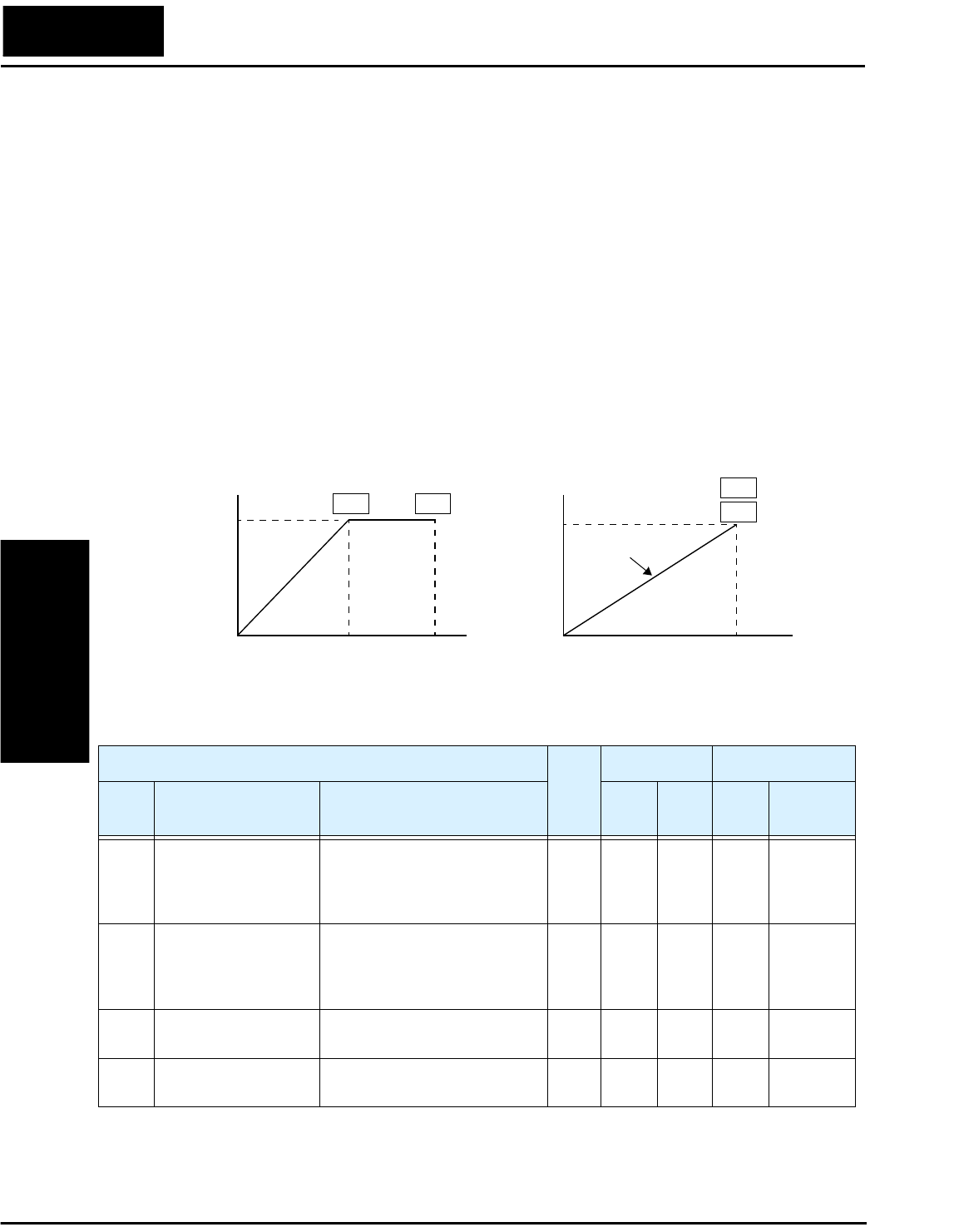
The base frequency and maximum frequency settings interact according to the graph
below (left). The inverter output operation follows the constant V/F curve until it reaches
the full-scale output voltage. This initial straight line is the constant-torque part of the
operating characteristic. The horizontal line over to the maximum frequency serves to let
the motor run faster, but at a reduced torque. If you want the motor to output constant
torque over its entire operating range (limited to the motor nameplate voltage and
frequency rating), then set the base frequency and maximum frequency equal as shown
(below right).
100%
0
V
Base
Frequency
Maximum
Frequency
A03 A04
f
100%
0
V
Base frequency =
maximum frequency
A03
A04
f
Constant torque
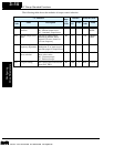
“A” Function
Run-
time
Edit
Defaults DOP,DRW,DOP+
Func.
Code
Name Description
EU/
US
Units
Func.
Code
Name
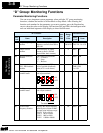
A01 Frequency source
setting
Three options; select codes:
00...Keypad potentiometer
01...Control terminal
02...Function F01 setting
✘
01 — Mon. F-SET-
SELECT
A02 Run command source
setting
Two options; select codes:
01...Control terminal
02...Run key on keypad, or
digital operator
✘
01 — Mon. F/R-
SELECT
A03 Base frequency
setting
Settable from 50 Hz to the
maximum frequency
✘
50/60 Hz F-00 F-BASE
A04 Maximum frequency
setting
Settable from the base
frequency up to 360 Hz
✘
50/60 Hz F-01 F-MAX
Technologies Inc.
Toll Free: voice: 1-877-539-2542 fax: 1-800-539-2542 www.mgitech.com