L100 Inverter
Configuring
Drive Parameters
3–9
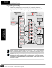
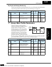
Trip Event and History Monitoring
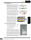
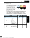
The trip event and history monitoring feature lets you cycle through related information
using the keypad. More details about trip event monitoring are on page 6–5.
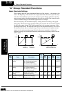
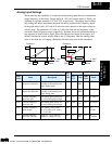
“F” Group: Main Profile Parameters
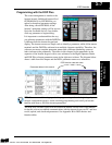
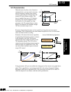
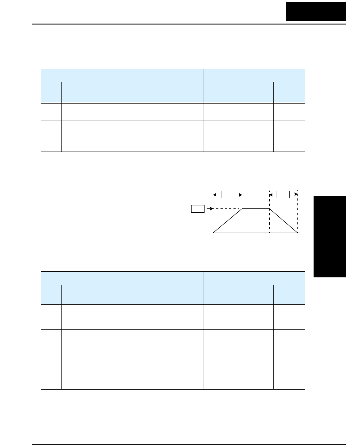
The basic frequency (speed) profile is
defined by parameters contained in the “F”
group as shown to the right. The set
running frequency is in Hz, but accelera-
tion and deceleration are specified in the
time duration of the ramp (from zero to
maximum frequency, or from maximum
frequency to zero). The motor direction
parameter determines whether the keypad
Run key produces a FWD or REV command. This parameter does not affect the intelli-
gent terminal FWD and REV functions, which are already separate.
“D” Function
Run-
time
Edit
Range
and
Units
DOP,DRW,DOP+
Func.
Code
Name Description
Func.
Code
Name
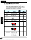
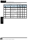
D08 Trip event monitor Displays the current trip event.
information.
——Mon. ERR1
D09 Trip history monitor Displays the previous two
events and their causes.
——Mon. ERROR
COUNT,
ERR2,
ERR3
Output
frequency
F01
time
F02 F03
“F” Function
Run-
time
Edit
Range
and
Units
DOP,DRW,DOP+
Func.
Code
Name Description
Func.
Code
Name
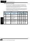
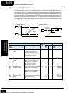
F01 Output frequency
setting
Standard default target
frequency that determines
constant motor speed
✔
0 to 360
Hz
Mon. FS, 2FS,
TH, VR,
1 to 15S
F02 Acceleration 1 Standard default acceleration
✔
0.1 to
3000 sec.
Mon. ACC1
F03 Deceleration 1 Standard default deceleration
✔
0.1 to
3000 sec.
Mon. DEC1
F04 Motor direction Two options; select codes:
00 .. Forward
01 .. Reverse
✘
00, 01 Mon. F/R-Select
Technologies Inc.
Toll Free: voice: 1-877-539-2542 fax: 1-800-539-2542 www.mgitech.com


