


L100 Inverter
Configuring
Drive Parameters
3–23
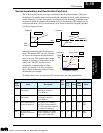
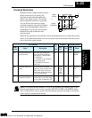
Overload Restriction
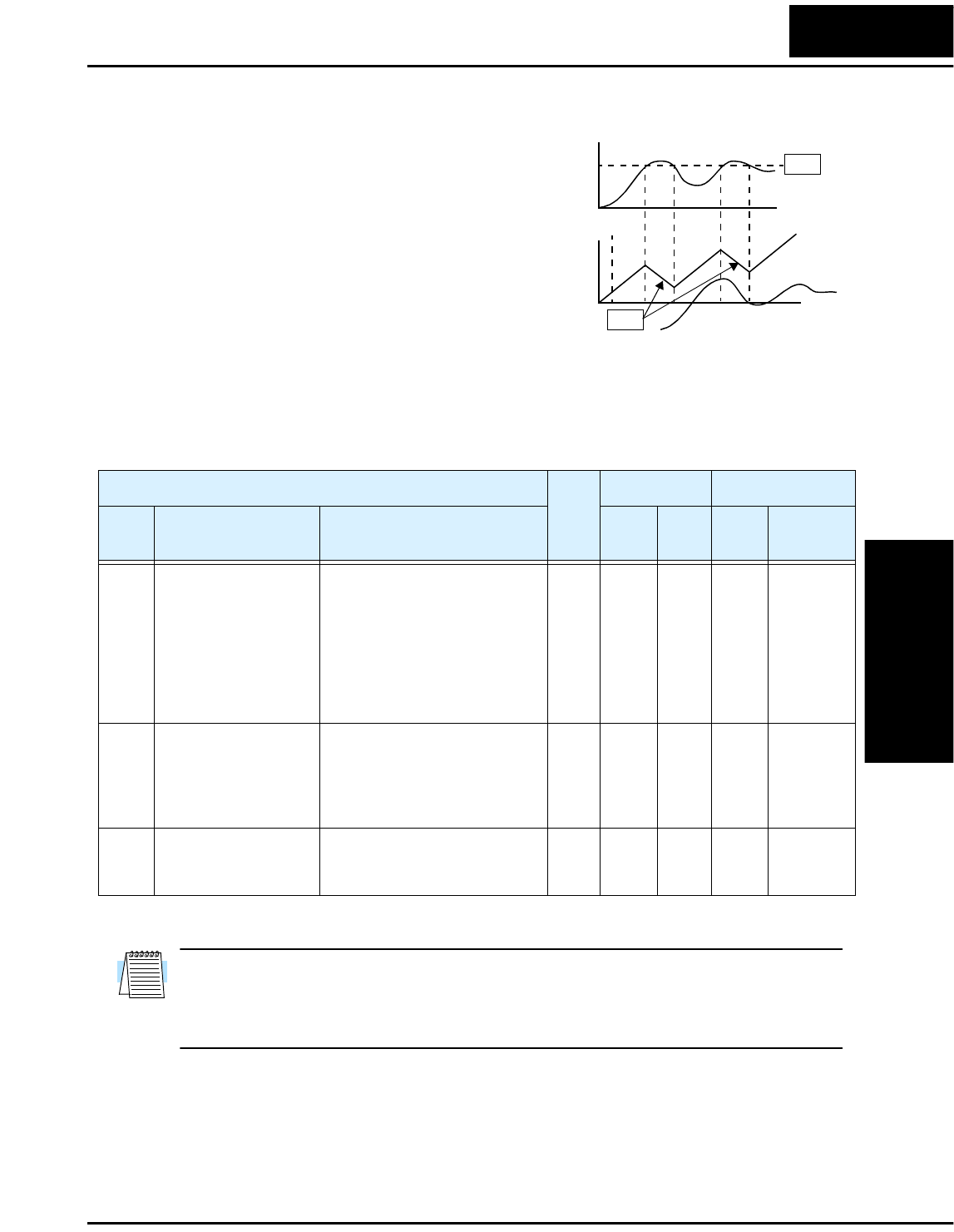
When the inverter output current exceeds a
preset current level you specify, the
overload restriction feature arbitrarily
reduces the output current. This feature
does not generate an alarm or trip event.
You can instruct the inverter to apply
overload restriction only during constant
speed, thus allowing higher currents for
acceleration. Or, you may use the same
threshold for both acceleration and
constant speed.
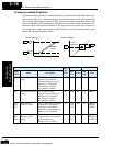
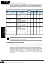
When the inverter detects an overload, it must decelerate the motor to reduce the current
until it is less than the threshold. You can choose the rate of deceleration that the inverter
uses to lower the output current.
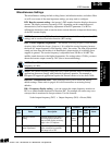
NOTE: For inverter models 005NFE, 011NFE, and 030HFE, the thermal value is less
than the rated amperes (is the same as models 004NFE, 007NFE, and 040HFE respec-
tively). Therefore, be sure to set the electronic thermal overload according to the actual
motor driven by the particular inverter.
0
Motor
Current
B23
B22
time
V
Output
frequency
restriction area
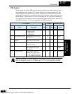
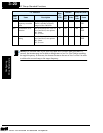
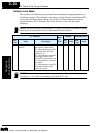
“B” Function
Run-
time
Edit
Defaults DOP,DRW,DOP+
Func.
Code
Name Description
EU/
US
Units
Func.
Code
Name
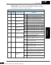
B21 Overload restriction
operation mode
Select the operating mode
during overload conditions,
three options, option codes:
00...Disabled
01...Enabled for acceleration
and constant speed
02...Enabled for constant
speed only
✘
01 — F24 OLOAD
MODE
B22 Overload restriction
setting
Sets the level for overload
restriction, between 50% and
150% of the rated current of
the inverter, setting resolution
is 1% of rated current
✘
rated
Amps
*1.25
See
*Note
A F24 OLOAD
LV L
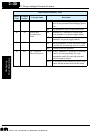
B23 Deceleration rate at
overload restriction
Sets the deceleration rate when
inverter detects overload, range
is 0.1 to 30.0, resolution is 0.1.
✘
1.0 — F24 OLOAD
CONST
Technologies Inc.
Toll Free: voice: 1-877-539-2542 fax: 1-800-539-2542 www.mgitech.com