


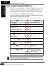
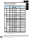


Maintenance and Inspection
Troubleshooting
and Maintenance
6–12
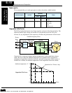
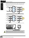
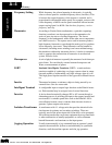
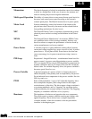
The figures below show measurement locations for voltage, current, and power measure-
ments listed in the table on the previous page. The voltage to be measured is the funda-
mental wave effective voltage. The power to be measured is the total effective power.
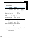
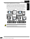
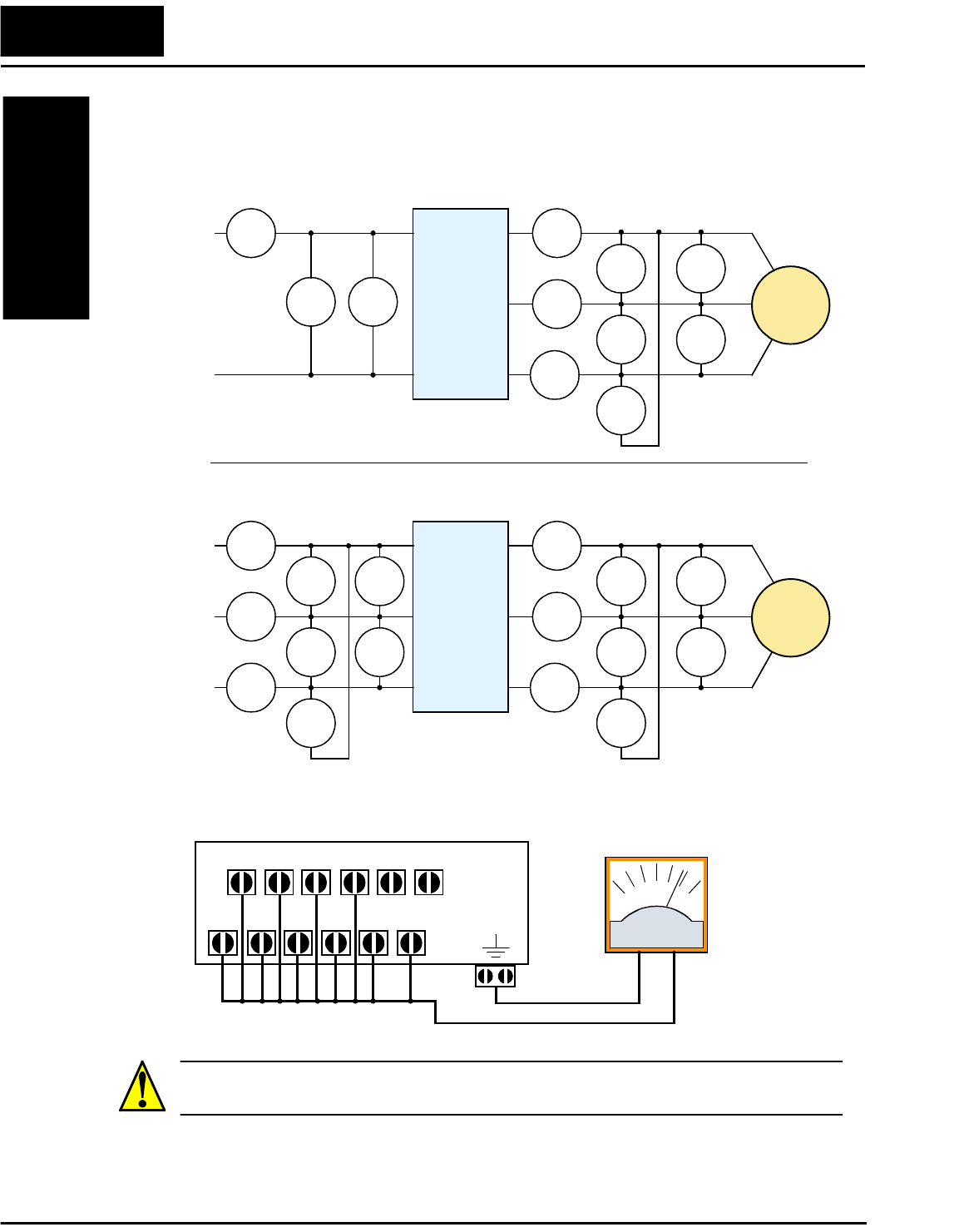
Conduct the insulation resistance test by short circuiting the terminals as shown below.
CAUTION: Never test the withstand voltage (HIPOT) on the inverter. The inverter has a
surge protector between the main circuit terminals above and the chassis ground.
E
1
W
1
I
1
I
1
I
1
I
1
E
U-V
E
U-V
E
U-V
W
01
W
02
INVERTER
MOTOR
L
1
N
U/T1
V/T2
W/T3
L
1
N
Single-phase measurement diagram
E
1
I
1
I
1
I
1
I
1
E
U-V
E
U-V
E
U-V
W
01
W
02
INVERTER
MOTOR
L1
N
U/T1
V/T2
W/T3
L1
N
Three-phase measurement diagram
W
01
W
02
E
1
E
1
I
2
I
3
L2
U
V
W
Meg ohm meter
L1 L2 L3 U V W
RB +1 + –
Technologies Inc.
Toll Free: voice: 1-877-539-2542 fax: 1-800-539-2542 www.mgitech.com