


L100 Inverter
Inverter Mounting
and Installation
2–25
Powerup Test Observations and Summary
Step 10: Reading this section will help you make some useful observations when first
running the motor.
Error Codes - If the inverter displays an error code (LED format is “Exx”), see the
instructions on page 6–5 to interpret and clear the error.
Acceleration and Deceleration - The L100 inverter has programmable acceleration and
deceleration values. The test procedure left these at the default value, 10 seconds. You
can observe this by setting the potentiometer at about half speed before running the
motor. Then press RUN, and the motor will take 5 seconds to reach a steady speed. Press
the STOP key to see a 5 second deceleration to a stop.
State of Inverter at Stop - If you adjust the motor’s speed to zero, the motor will slow to
a near stop, and the inverter turns the outputs off. The high-performance L100 can rotate
at a very slow speed with high torque output, but not zero (must use servo systems with
position feedback for that feature). This characteristic means you must use a mechanical
brake for some applications.
Interpreting the Display - First, let’s interpret the output frequency display readout.
The maximum frequency setting (parameter A4) defaults to 50Hz or 60 Hz (Europe and
United States, respectively) for your application.
Example: Suppose a 4-pole motor is rated for 60 Hz operation, so the inverter is config-
ured to output 60 Hz at full scale. Let’s use the following formula to calculate the RPM.
The theoretical speed for the motor is 1800 RPM (speed of torque vector rotation).
However, the motor cannot generate torque unless its shaft turns at a slightly different
speed. This difference is called slip. So it’s common to see a rated speed of approxi-
mately 1750 RPM on a 60 Hz, 4-pole motor. Using a tachometer to measure shaft speed,
you can see the difference between the inverter output frequency and the actual motor
speed. The slip increases slightly as the motor’s load increases. This is why the inverter
output value is called “frequency,” since it is not exactly equal to motor speed. You can
program the inverter to display output frequency in units more directly related to the load
speed by entering a constant (discussed more in depth on page 3–25).
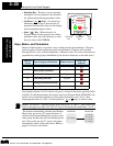
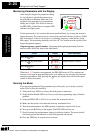
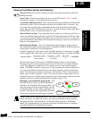
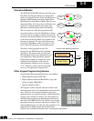
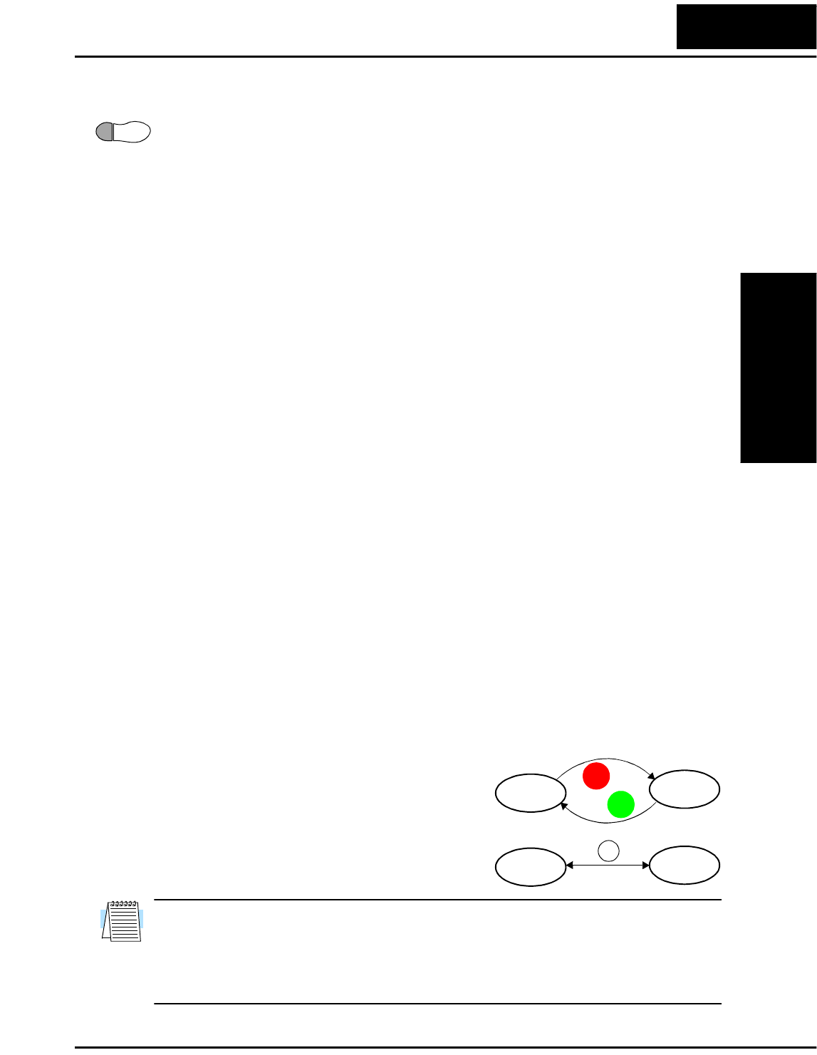
Run/Stop versus Monitor/Program modes – The
Run LED on the inverter is On in the Run Mode,
and Off in the Stop Mode. The Program LED is On
when the inverter is in the Program Mode, and Off
for Monitor Mode. All four mode combinations are
possible. The diagram to the right depicts the modes
and the mode transitions from keypad commands.
NOTE: Some factory automation devices such as PLCs have alternate Run/Program
modes; the device is in either one mode or the other. In the Hitachi inverter, however,
Run Mode alternates with Stop Mode, and Program Mode alternates with Monitor
Mode. This arrangement lets you program some values while the inverter is operating —
providing flexibility for maintenance personnel.
10
Speed in RPM
Frequency 60×
Pairs of poles
----------------------------------------
Frequency 120×
# of poles
-------------------------------------------
60 120×
4
---------------------1800RPM== ==
Run
Stop
Monitor Program
RUN
STOP
STOPSTOP
STOP
RESET
FUNC.
Technologies Inc.
Toll Free: voice: 1-877-539-2542 fax: 1-800-539-2542 www.mgitech.com