


L100 Inverter
Configuring
Drive Parameters
3–33
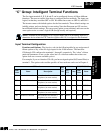
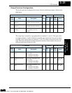
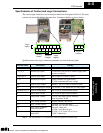
Analog Summary Table - this table shows all three functions for the analog output FM
(frequency meter) terminal at a glance. Detailed descriptions, related parameters and
settings, and example wiring diagrams are in Chapter 4, starting on page 4–24.
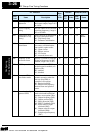
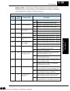
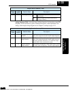
05 AL Alarm signal ON when an alarm signal has occurred and has not
been cleared
OFF when no alarm has occurred since the last
clearing of alarm(s)
Output Function Summary Table
Option
Code
Terminal
Symbol
Function Name
Description
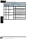
Analog Function Summary Table
Option
Code
Terminal
Symbol
Function Name
Description
00 A-F Analog frequency
monitor
PWM (pulse-width-modulated) voltage output which has
a duty cycle proportional to the inverter output frequency
01 A Analog current
output monitor
PWM (pulse-width-modulated) voltage output which has
a duty cycle proportional to the inverter output current to
the motor. It reaches 100% duty cycle when the output
reaches 200% of the rated inverter current.
02 D Digital frequency
output monitor
FM (frequency-modulated) voltage output with a constant
50% duty cycle. Its frequency = inverter output frequency.
Technologies Inc.
Toll Free: voice: 1-877-539-2542 fax: 1-800-539-2542 www.mgitech.com