


Using Intelligent Output Terminals
Operations
and Monitoring
4–18
Using Intelligent Output Terminals
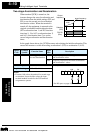
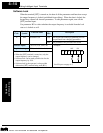
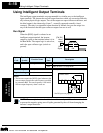
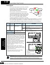
The intelligent output terminals are programmable in a similar way to the intelligent
input terminals. The inverter has several output functions which you can assign individu-
ally to three physical logic outputs. Two of the outputs are open-collector transistors, and
the third output is the alarm relay (form C – normally open and normally closed
contacts). The relay is assigned the alarm function by default, but you can assign it to
any of the functions that the open-collector outputs can use as well.
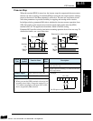
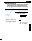
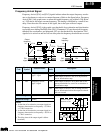
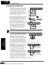
Run Signal
When the [RUN] signal is selected as an
intelligent output terminal, the inverter
outputs a signal on that terminal when it is in
the Run Mode. The output logic is active low,
and is the open collector type (switch to
ground).
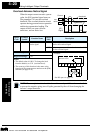
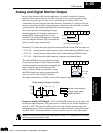
NOTE: The example circuit in the table above drives a relay coil. Note the use of a diode
to prevent the negative-going turn-off spike generated by the coil from damaging the
inverter’s output transistor.
time
[FW, RV]
B82
Motor
speed
Run
Signal
start freq.
ON
Option
Code
Terminal
Symbol
Function Name
Output
State
Description
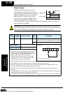
00 RUN Run signal ON when inverter is in Run Mode
OFF when inverter is in Stop Mode
Valid for outputs:
11, 12, AL0 – AL2
Required settings:
(none)
Notes:
•
The inverter outputs the [RUN] signal whenever the
inverter output exceeds the start frequency specified
by parameter B82
.
The start frequency is the initial
inverter output frequency when it turns on.
CM2
1112
FM
H OIO L
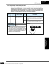
Example:
RUN
RY
+
–
Inverter output
terminal circuit
See I/O specs on page 4–5.
Technologies Inc.
Toll Free: voice: 1-877-539-2542 fax: 1-800-539-2542 www.mgitech.com