


L100 Inverter
Inverter Mounting
and Installation
2–7
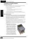
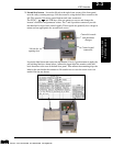
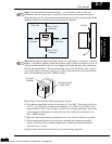
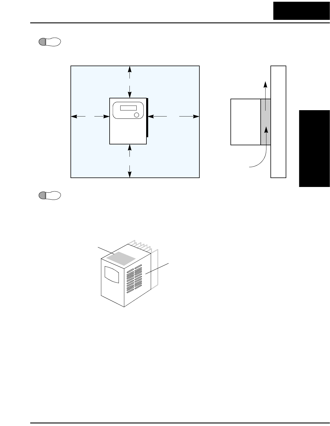
Step 2: To summarize the caution messages — you will need to find a solid, non-
flammable, vertical surface that is a relatively clean and dry environment. In order to
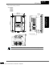
ensure enough room for air circulation around the inverter to aid in cooling, maintain the
specified clearance around the inverter specified in the diagram.
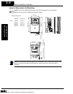
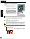
Step 3: Before proceeding to the wiring section, it’s a good time to temporarily cover the
inverter’s ventilation openings. Paper and masking tape is all that is needed to do this. It
will prevent harmful debris such as wire clippings and metal shavings from entering the
inverter during installation. The inverter housing comes from the factory with a snap-in
cover on the top of its housing. Ensure it is in place at this time (also to be removed later,
unless the installation must have a NEMA rating).
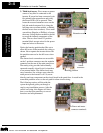
Please observe this checklist while mounting the inverter:
1. The ambient temperature must be in the range of -10 to 40°C. If the range will be up
to 50°C, you will need to set the carrier frequency to 2.1 kHz or less and derate the
output current to 80% or less. Chapter 3 covers how to change parameters such as the
carrier frequency. Remember to remove the top cover (unless the installation is to
have a NEMA rating)!
2. Keep any other heat-producing equipment as far away from the inverter as possible.
3. When installing the inverter in an enclosure, maintain the clearance around the
inverter and verify that its ambient temperature is within specification when the
enclosure door is closed.
4. Do not open the main front panel door at any time during operation.
2
L100
8 cm (3.15”)
minimum
10 cm (3.94”)
minimum
12 cm (4.72”)
minimum
10 cm (3.94”)
minimum
Clear area
Air flow
3
Ventilation holes
(both sides)
Top cover
installed
Technologies Inc.
Toll Free: voice: 1-877-539-2542 fax: 1-800-539-2542 www.mgitech.com