L100 Inverter
Configuring
Drive Parameters
3–13
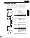
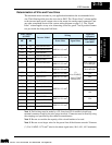
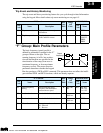
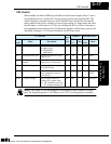
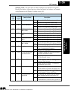
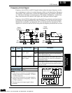
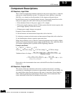
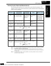
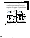
V/F Characteristics
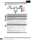
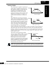
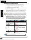
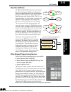
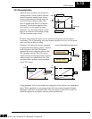
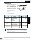
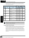
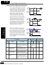
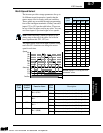
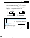
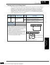
When the motor load has a lot of inertia or
starting friction, you may need to increase
the low frequency starting torque charac-
teristics by boosting the voltage above the
normal V/F ratio (shown at right). The
boost is applied from zero to 1/2 the base
frequency. You set the breakpoint of the
boost (point A on the graph) by using
parameter A43. The manual boost is calcu-
lated as an addition to the standard straight
V/F line (constant torque curve).
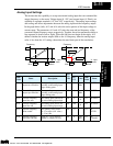
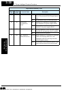
Be aware that running the motor at a low speed for a long time can cause motor
overheating. This is particularly true when manual torque boost is on, or if the motor
relies on a built-in fan for cooling.
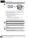
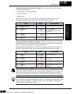
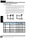
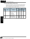
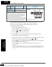
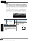
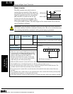
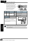
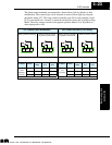
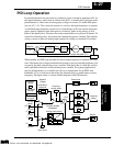
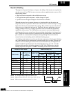
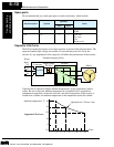
Parameter A44 selects the inverter algorithm
for generating the frequency output, as shown
in the diagram to the right. The inverter
generates the motor output according to the
V/F algorithm selected. The V/F curve is
oriented toward developing constant torque or
reduced torque (see graph below, left). You
can select either constant torque or reduced
torque V/F control.
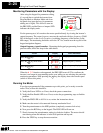
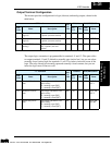
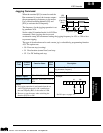
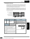
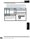
Using parameter A45 you can modify the voltage gain of the inverter (see graph above,
right). This is specified as a percentage of the full scale setting (Automatic Voltage
Regulation) AVR level in parameter-F03. The gain can be set from 20% to 100%. It
should be adjusted in accordance with the motor specifications.
V
f base =
60Hz
A42 = 11
A43 = 10.0%
100%
frequency
6.0Hz
0
11.8%
30.0Hz
Torque boost
A
Output
Variable freq. control,
constant torque
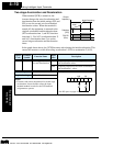
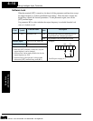
Inverter PWM Switching Algorithms
A44
Variable freq. control,
reduced torque
V
Constant
torque
100%
frequency
0
Reduced
torque
A45
V
100%
frequency
0
20%
A44 = 00
A44 = 01
Technologies Inc.
Toll Free: voice: 1-877-539-2542 fax: 1-800-539-2542 www.mgitech.com