


L100 Inverter
Inverter Mounting
and Installation
2–21
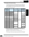
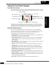
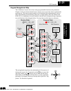
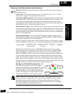
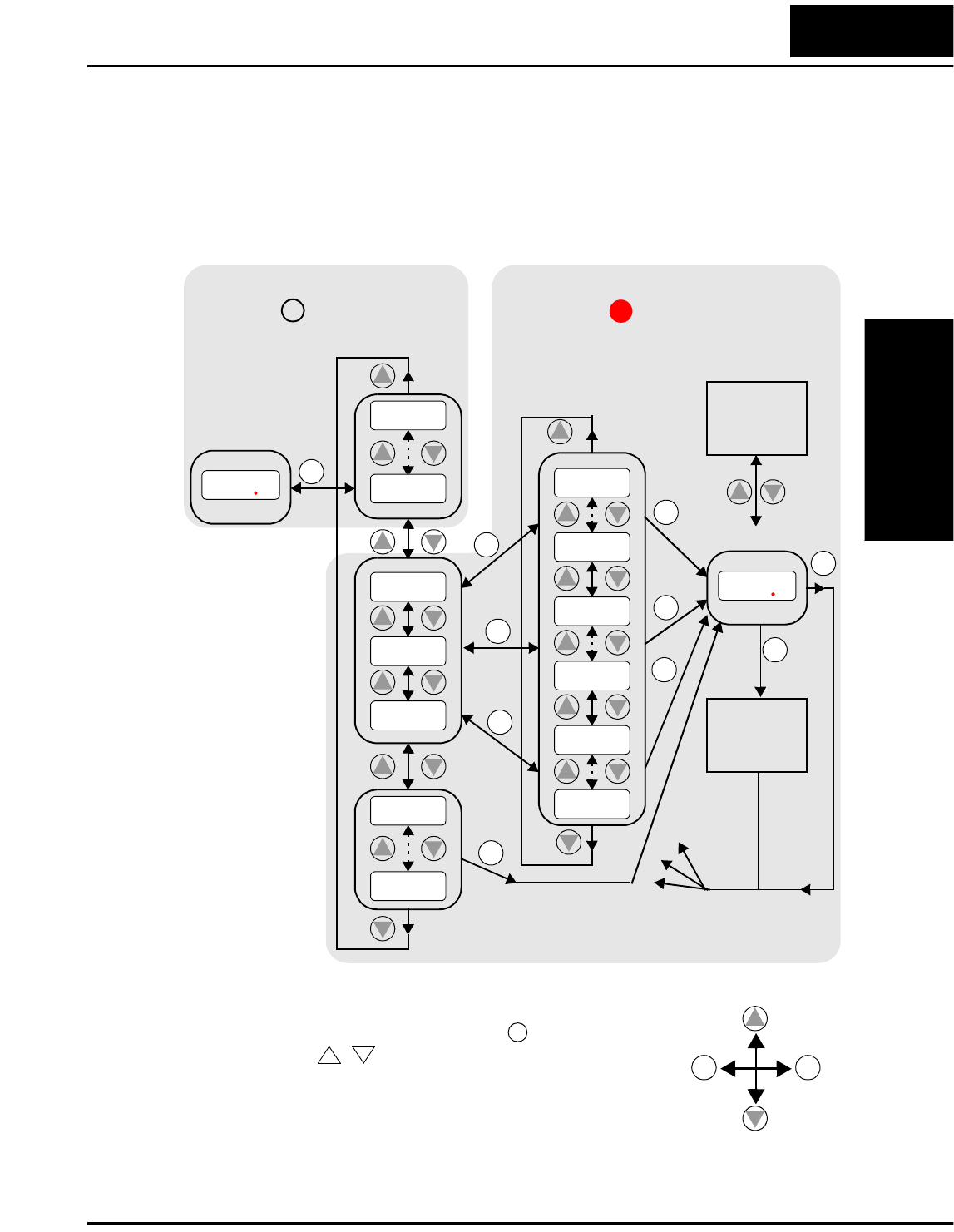
Keypad Navigational Map
The L100 Series inverter drives have many programmable functions and parameters.
Chapter 3 will cover these in detail, but we need to access just a few items to perform the
powerup test. The menu structure makes use of function codes and parameter codes to
allow programming and monitoring with only a 4-digit display and a few buttons and
LEDs. So, it is important to become familiar with the basic navigational map of parame-
ters and functions in the diagram below. You may later use this map as a reference.
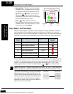
The navigational map shows the relationship of all resources of
the inverter in one view. In general, use the key to move left
and right, and the (arrow) keys to move up and down.
Other tables in this chapter will show how to set up a particular
parameter, for example. However, the map above gives the “big
picture” for functions in general.
0000
1
2
Monitor Mode
09D
2
1
Program Mode
01D
--C
--B
--A
04F
01F
91C
01C
92B
01B
98A
01A
3241
Edit
Write
data to
EEPROM
Increment/
decrement
value
2
1
2
1
2
1
2
1
2
1
2
1
1
Select ParameterSelect Function
Display
Data
2
PRG LED = OFF
PRG LED = ON
Return to
parameter
list
2
1
2
1
2
1
2
1
2
1
Edit Parameter
FUNC.
FUNC.
FUNC.
FUNC.
FUNC.
FUNC.
FUNC.
FUNC.
FUNC.
STR
2
1
FUNC. FUNC.
FUNC.
1
2
Technologies Inc.
Toll Free: voice: 1-877-539-2542 fax: 1-800-539-2542 www.mgitech.com