


“D” Group: Monitoring Functions
Configuring
Drive Parameters
3–8
“D” Group: Monitoring Functions
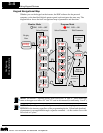
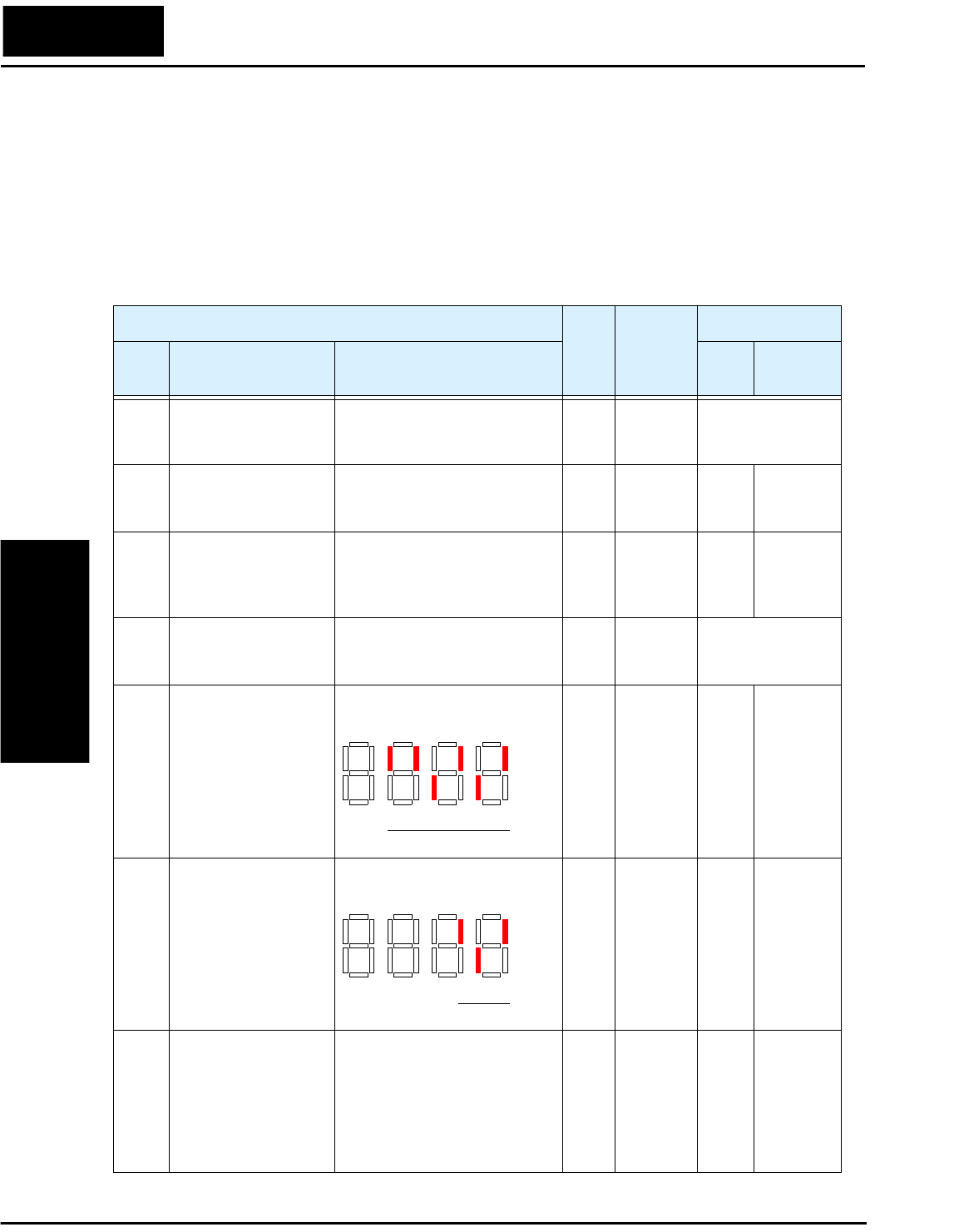
Parameter Monitoring Functions
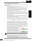
You can access important system parameter values with the “D” group monitoring
functions, whether the inverter is in Run Mode or Stop Mode. After selecting the
function code number for the parameter you want to monitor, press the Function key
once to show the value on the display. In Functions D05 and D06, the intelligent termi-
nals use individual segments of the display to show On/Off status.
“D” Function
Run-
time
Edit
Range
and
Units
DOP,DRW,DOP+
Func.
Code
Name Description
Func.
Code
Name
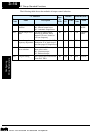
D01 Output frequency
monitor
Real-time display of output
frequency to motor, from 0.0 to
360.0 Hz
— 0.0 to
360.0 Hz
Monitor: FS, 2FS,
TM, VR, 1 to 15 S
D02 Output current
monitor
Filtered display of output
current to motor (100 mS
internal filter time constant)
— A Mon. Im
D03 Rotation direction
monitor
Three different indications:
“F”..... Forward
“| |” .. Stop
“r”..... Reverse
——Mon. VR
D04 Process variable
(PV), PID feedback
monitor
Displays the scaled PID
process variable (feedback)
value (A75 is scale factor)
——Monitor: FSP, 2FP,
TMP, VRP,
1 to 15S
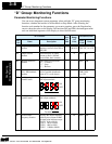
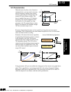
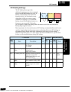
D05 Intelligent input
terminal status
Displays the state of the intelli-
gent input terminals:
——Mon. TERM
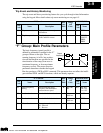
D06 Intelligent output
terminal status
Displays the state of the intelli-
gent output terminals:
——Mon. TERM
D07 Scaled output
frequency monitor
Displays the output frequency
scaled by the constant in B86.
Decimal point indicates range:
XX.XX 0.01 to 99.99
XXX.X 100.0 to 999.9
XXXX. 1000 to 9999
XXXX 10000 to 99990
— Hz Mon. /Hz
ON
OFF
123456
Terminal numbers
ON
OFF
1112
Terminal numbers
AL
Technologies Inc.
Toll Free: voice: 1-877-539-2542 fax: 1-800-539-2542 www.mgitech.com