


Analog Input Operation
Operations
and Monitoring
4–24
Analog Input Operation
The L100 inverters provide for analog input to
command the inverter frequency output value.
The analog input terminal group includes the
L, OI, O, and H terminals on the control
connector, which provide for Voltage [O] or
Current [OI] input. All analog input signals
must use the analog ground [L].
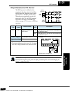
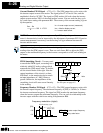
If you use either the voltage or current analog
input, you must select one of them using the
logic input terminal function [AT] analog
type. If terminal [AT] is Off, the voltage input
[O] can command the inverter output
frequency. If terminal [AT] is On, the current
input [OI] can command the inverter output
frequency. The [AT] terminal function is
covered in the logic input section on page
4–15. Remember that you must also set
A01 = 01 to select analog input as the
frequency source.
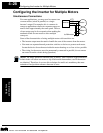
NOTE: If no logic input terminal is configured for the [AT] function, then inverter sums
the voltage and current input to determine the desired input value.
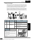
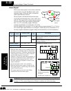
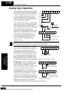
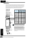
Using an external potentiometer is a popular
way to control the inverter output frequency
(and a good way to learn how to use the
analog inputs). The potentiometer uses the
10V reference [H] and the analog ground [L]
for excitation, and the voltage input for the
signal. By default, the [AT] terminal selects
the voltage input when it is Off. Take care to
use the proper resistance for the potentiometer, which is 1 to 2 k Ohms, 2 Watts.
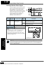
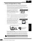
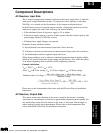
Voltage Input – The voltage input circuit
uses terminals [L] and [O]. Attach the cable
shield wire only to terminal [L] on the
inverter. Maintain the voltage within specifi-
cations (do not apply negative voltage).
Current Input – The current input circuit
uses terminals [OI] and [L]. The current come
from a sourcing type transmitter; a sinking
type will not work! This means the current
must flow into terminal [OI], and terminal [L]
is the return back to the transmitter. The input
impedance from [OI] to [L] is 250 Ohms.
Attach the cable shield wire only to terminal [L] on the inverter.
1112
CM2FM
O LOIH
+V Ref.
A GND
Voltage input
Current input
1112
CM2FM
O LOIH
+ –
4-20 mA, AT= On
0-10 V, AT= Off
A01
[AT]
V/I input
select
Frequency
setting
1112
CM2FM
O LOIH
1 to 2 k Ohms, 2 Watts
1112
CM2FM
O LOIH
+ –
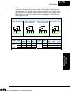
4 to 19.6 mA DC,
4 to 20 mA nominal
0 to 9.6 VDC,
0 to 10V nominal
1112
CM2FM
O LOIH
See I/O specs on page 4–5.
Technologies Inc.
Toll Free: voice: 1-877-539-2542 fax: 1-800-539-2542 www.mgitech.com