


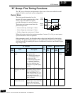
“B” Group: Fine Tuning Functions
Configuring
Drive Parameters
3–22
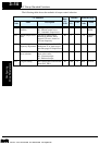
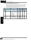
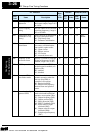
Electronic Thermal Overload Alarm Setting
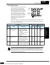
The thermal overload detection protects
the inverter and motor from excessive heat.
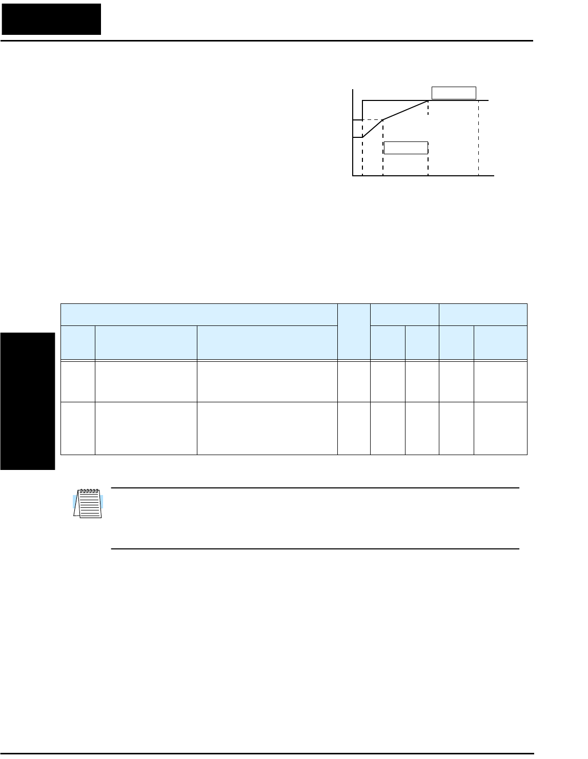
First use B13 to select the torque charac-
teristic as a function of frequency. For
example, a motor can overheat if it runs for
too long at a low speed. You can counter-
act this effect by reducing the torque at
low speed. Otherwise, use the constant
torque characteristic.
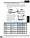
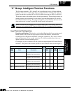
The torque developed in a motor is directly proportional to the current in the windings,
which is also proportional to the heat generated (and temperature, over time). Therefore,
you must set the thermal overload threshold in terms of current (amperes) for parameter
B12. The range is 50% to 120% of the rated current for each model of inverter. If the
current exceeds the level you specify, the inverter will trip and log an event (error E5) in
the history table. The inverter turns the motor output off when tripped.
NOTE: For inverter models 005NFE, 011NFE, and 030HFE, the thermal value is less
than the rated amperes (is the same as models 004NFE, 007NFE, and 040HFE respec-
tively). Therefore, be sure to set the electronic thermal overload according to the actual
motor driven by the particular inverter.
100%
0
To r q u e
Output frequency
B13 = 01
Hz
80%
60%
520 60
120
Constant torque
Reduced
torque
B13 = 00
“B” Function
Run-
time
Edit
Defaults DOP,DRW,DOP+
Func.
Code
Name Description
EU/
US
Units
Func.
Code
Name
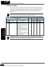
B12 Level of electronic
thermal setting
Set a level between 50% and
120% for the rated inverter
current.
✘
rated
Amps
*Note
% F-23 E-THM
LV L
B13 Electronic thermal
characteristic
Select from two curves, option
codes:
00...(SUB) reduced torque
01...(CRT) constant torque
✘
01 A F-23 E-THM
Char Sub
Technologies Inc.
Toll Free: voice: 1-877-539-2542 fax: 1-800-539-2542 www.mgitech.com