


L100 Inverter
Configuring
Drive Parameters
3–31
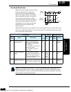
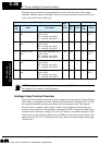
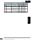
Output Terminal Configuration
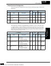
The inverter provides configuration for logic (discrete) and analog outputs, shown in the
table below.
The output logic convention is programmable for terminals 11 and 12. The open-collec-
tor output terminals 11 and 12 default to normally open (active low), but you can select
normally closed (active high) for terminals 11 and 12 in order to invert the sense of the
logic. The relay already has normally open and normally closed contacts, but you can
invert the logic sense of these as well.
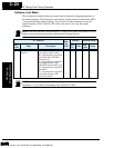
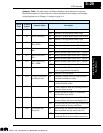
“C” Function
Run-
time
Edit
Defaults DOP,DRW,DOP+
Func.
Code
Name Description
EU/
US
Units
Func.
Code
Name
C21 Terminal 11 function
(logical)
Select function for terminal 11,
6 options (see next section)
✘
01 — F-35 OUT-TM
1
C22 Terminal 12 function
(logical)
Select function for terminal 12,
6 options (see next section)
✘
00 — F-35 OUT-TM
2
C23 Terminal FM function
(analog)
Select function for terminal
FM, 3 options (see next
section)
✘
00 — F-37
MONITOR
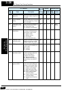
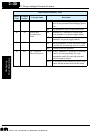
“C” Function
Run-
time
Edit
Defaults DOP,DRW,DOP+
Func.
Code
Name Description
EU/
US
Units
Func.
Code
Name
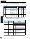
C31 Terminal 11 active
state
Select logic convention, two
option codes:
00...normally open [NO]
01...normally closed [NC]
✘
00 — F-35 OUT-TM
O/C-1
C32 Terminal 12 active
state
Select logic convention, two
option codes:
00...normally open [NO]
01...normally closed [NC]
✘
00 — F-35 OUT-TM
O/C-2
C33 Alarm relay active
state
Select logic convention, two
option codes:
00...normally open [NO]
01...normally closed [NC]
✘
01 — F-35 OUT-TM
O/C-RY
Technologies Inc.
Toll Free: voice: 1-877-539-2542 fax: 1-800-539-2542 www.mgitech.com