


L100 Inverter
Operations
and Monitoring
4–25
Analog and Digital Monitor Output
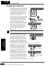
In the system design for the inverter application, it is useful to monitor the inverter
operation from a remote location. In some cases, this is only a panel-mounted analog
meter (moving-coil type). In other cases, a controller device such as a PLC may
command the inverter frequency and other functions. Sometimes it is useful to have the
inverter transmit the (real-time) output frequency value back to the controller to confirm
actual operation. The analog output function serves these purposes.
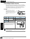
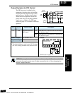
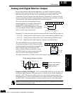
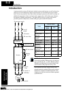
The inverter provides an analog/digital output
terminal primarily for frequency monitoring on
terminal [FM] (frequency monitor). It uses
terminal [L] as analog GND reference. If needed,
you can configure terminal [FM] to transmit the
inverter current output value instead.
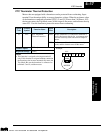
Parameter C23 selects the output signal data and transmission format. The selections are:
• C23 = 00 Analog monitor output frequency, pulse-width modulated (PWM) format
• C23 = 01 Analog monitor output current, pulse-width modulated (PWM) format
• C23 = 02 Digital monitor output frequency, frequency-modulated format
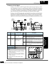
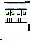
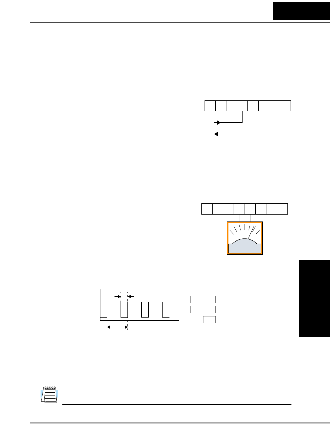
The analog PWM signals are primarily designed
for driving a moving-coil meter. The pulse-width
modulated signal is automatically averaged by the
inertia of the moving-coil mechanism. The
meter’s indicator needle mechanically converts
the PWM signal to an analog representation. Be
sure to use a 10V full-scale DC voltmeter.
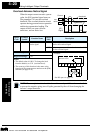
The signal characteristics of [FM] for each of the output formats are shown below:
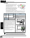
Frequency Monitor, PWM Signal – (C23 = 00) The [FM] output duty cycle varies with
the inverter output frequency. The signal period T is fixed at 4 ms, and the amplitude is
fixed at 10 VDC. The signal on [FM] reaches full scale when the inverter outputs the
maximum frequency. You can scale the duty cycle with a scale factor setting with param-
eter B81. This is a dedicated indicator, so that it cannot be used as a line speed signal.
NOTE: The indicator accuracy after adjustment is about ±5%. Depending on the motor,
the accuracy may exceed this value.
1112
CM2FM
O LOIH
A GND
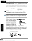
Analog/digital Output
See I/O specs on page 4–5.
1112
CM2FM
O LOIH
+–
0 to 10V,
1 mA
C23 = 00
C23 = 01
0 V
Inverter output current
time
[FM]
10V
T
t
Output value
t
T
---=
Inverter output frequency
Pulse-width modulation (analog)
B81
PWM scale factor
T = 4 ms
Technologies Inc.
Toll Free: voice: 1-877-539-2542 fax: 1-800-539-2542 www.mgitech.com