L100 Inverter
Inverter Mounting
and Installation
2–3
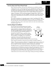
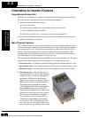
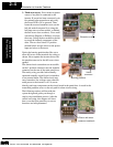
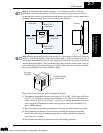
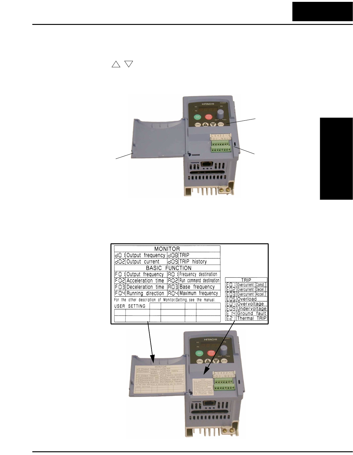
2. Second-level access - Locate the lift tab at the right lower corner of the front panel
near the safety warning message. Lift the corner to swing the half-door around to the
left. This exposes four more control buttons and some connectors.
The FUNC., , , and STR keys allow an operator to access and change the
inverter’s functions and parameter values. The 7 and 8-position connectors provide
the interface for logic-level control signals. These signals are generally low-voltage in
nature and are appropriate for second-level access.
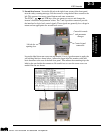
Locate the label sheet that came with the manual. This is a good moment to apply the
self-sticking labels as shown below. Adhere the larger label for monitor codes and
basic functions to the rear of the half-door panel. Then adhere the remaining trip code
label to the area beside the connectors. Be careful not to cover the screw access on
models like the one shown.
1
2
Control signal
connectors
Lift tab for
opening door
Controls for mode
and parameter
changes
Technologies Inc.
Toll Free: voice: 1-877-539-2542 fax: 1-800-539-2542 www.mgitech.com


