


frame locations 2-3, 2-5, 2-6
frame naming standard 2-1
frame supervisor verification 3-5
front chassis cable, SPS 1-8
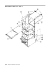
front view of 49-inch frame locations 2-4
front view of frame locations 2-3
front view of multi-switch frame locations 2-4
H
handling static-sensitive devices 4-1
I
installing adapter microcode packages 3-10
installing firmware updates on SP nodes 3-10
K
kerberos authentication 3-1
L
location diagrams of the RS/6000 SP components
component connector details 2-9
external cable routing 2-11
frame 2-6
frame cable routing path in rear of frame 2-9, 2-11
front view of 49-inch frame locations 2-4
front view of frame locations 2-3
front view of multi-switch frame locations 2-4
rear view of frame locations 2-5
locations
cable plug locations 2-1
connector details 2-1
location diagrams of RS/6000 SP components 2-1
M
major assembly naming standard 2-2
male wrap plug 1-4
microcode packages, installing adapter 3-10
multi-switch frame (F/C 2030/1) 5-11
multi-switch frame locations 2-4
N
naming standard
assembly 2-2
connector location 2-2
for RS/6000 SP components 2-1
format structure 2-1
frame 2-1
major assembly 2-2
node supervisor verification 3-4
nodes, fencing 3-8
nodes, unfencing 3-8
P
partitioning, SPS 3-8
partitioning, switch 3-8
Perspectives, verification tests using 3-4
placing a SPS assembly into service position 3-9
Procedures
ESD 3-1
purpose of book xv
task procedures overview xv
R
rear view of frame locations 2-5
removing 4-1
switch assembly 4-2
switch fans 4-3
switch front chassis cable 4-3
switch inner chassis cable 4-5
switch power card 4-6
switch supervisor card 4-4
the RS/6000 SP components 4-1
removing a switch assembly from the active
configuration 3-7
removing switch resources 3-7
replacing 4-1
switch assembly 4-2
switch fans 4-3
switch front chassis cable 4-4
switch inner chassis cable 4-6
switch power card 4-7
switch supervisor card 4-5
the RS/6000 SP components 4-1
replacing a SPS assembly from service position 3-9
Requirements
ESD 3-1
restoring a switch assembly to the active
configuration 3-8
restoring switch resources 3-7
S
selecting appropriate switch clocks 3-6
selecting the switch clock source 3-6
service position procedures 3-9
service procedures
placing a SPS assembly into service position 3-9
removing switch resources 3-7
replacing a SPS assembly from service position 3-9
restoring switch resources 3-7
selecting appropriate switch clocks 3-6
service position procedures 3-9
verification and isolation procedures
kerberos authentication 3-1
Service Request Number (SRN) table for SP Switch
adapters 1-24
SP Switch adapters, Service Request Number (SRN)
table 1-24
SP Switch environment MAP
flowcharted 1-5
SP Switch high-level diagram 1-2
X-2 RS/6000 SP: SP Switch Service Guide