


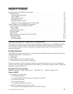
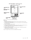
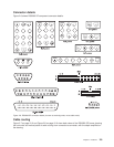

Connector details
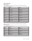
Figure 2-6 shows RS/6000 SP component connector details.
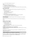
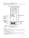
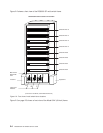
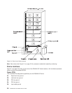
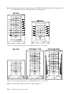
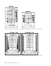
Cable routing
Figure 2-7 on page 2-10 and Figure 2-8 on page 2-10 show back views of the RS/6000 SP frame, showing
the horizontal and vertical paths of cable routing from connector-to-connector, with the depth amplified on
the drawing.
Figure 2-6. RS/6000 SP connector details (as seen at receiving ends, not at cable ends)
Chapter 2. Locations 2-9