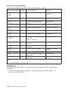
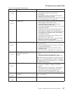
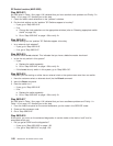
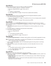
Note: When unplugging the two ends of the suspect cable, check /var/adm/SPlogs/css/out.top to
verify only two (2) ports were lost. If four (4) ports were lost, then two cables were swapped
across that switch to switch connection. Connect the cables correctly and check
/var/adm/SPlogs/css/out.top for any other errors.
2. If this is a switch-to-switch connection, have customer update the switch configuration file
appropriately (to show wrap plugs) before continuing:
v For code level 1.02 and higher, use the Etopology command.
3. Make sure processor nodes that were put in “Service” mode are returned to “Normal” mode. Make
sure all processor nodes are IPLed completely.
4. Have customer verify that the switch code is running on all processor nodes.
5. From the control workstation of the “primary” processor node, type Estart followed by ENTER.
6. Check /var/adm/SPlogs/css/out.top file for problems regarding the jacks indicated.
7. Does out.top file show a problem on any jacks indicated?
v If yes:
a. Problem is in the SP Switch which is still reporting a problem.
b. Go to “Step 0620-041” on page 1-35 to service or replace the switch assembly.
v If no:
a. If this is a switch-to-switch connection, remove both wrap plugs from the SP Switches.
b. Replace the frame-to-frame switch data cable that was disconnected before.
c. Go to “Step 0620-043” on page 1-36 to verify fix.
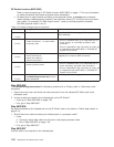
Step 0620-024
Problem reported with all switch data cables from one or more frames. This may be caused by a clocking
or grounding problem between frames.
Note: The “master-clock” switch indicates the switch which is supplying the master clock for the
system—the master clock will have the clock input multiplexor set to “internal clock” (0). A
“problem” switch indicates any switch which is experiencing problems.
1. Check the switch clock selections on the “problem” switches (refer to “Selecting appropriate switch
clocks” on page 3-6).
2. Do the clock settings on the “problem” SP Switches appear to be okay?
v If yes, go to “Step 0620-025”.
v If no:
a. Change the clock selections on the appropriate switches (refer to “Selecting appropriate switch
clocks” on page 3-6).
b. Go to “Step 0620-043” on page 1-36 to verify fix.
Step 0620-025
The clock settings on the “problem” SP Switches appear to be okay.
1. Is the problem switch in a frame with processor nodes?
2.
v If yes, go to “Step 0620-032” on page 1-32.
v If no, go to “Step 0620-026”.
Step 0620-026
Problem switch is in a switch frame (contains switches only, no processor nodes).
1. From Perspectives on the control workstation, open the Switch Front Panel window for this switch.
2. Check the clock selection to see if it is set to Internal or to one of the following external clocks:
v For SP switch types: “Jack3”, “Jack4”, or “Jack5”.
3. Is the clock selection set to one of the External clocks?
SP Switch function (MAP 0620)
1-30
RS/6000 SP: SP Switch Service Guide


