


3. Is the measured resistance now within the acceptable range?
v If yes, go to “Step 0600-017” on page 1-10 to verify fix.
v If no, go to “Step 0600-008”.
Step 0600-008
You replaced the inner chassis cable and the front chassis cable but the measured resistance is still
outside of the acceptable range.
1. This indicates that there is still a problem.
2. Replace the switch supervisor card.
3. Go to “Step 0600-017” on page 1-10 to verify fix.
Step 0600-009
You have voltage shutdown condition, the supervisor control cable appears to be okay, and the resistance
value you measured in Table 1-3 on page 1-6 was within an acceptable range. Based on these symptoms,
“Step 0600-005” on page 1-6 directed you to this location.
1. Reconnect cable S00-PC-P4 at switch power supply 1.
2. Repeat resistance measurement from “Step 0600-005” on page 1-6.
3. Is the measured resistance within the acceptable range?
v If yes, replace switch power supply 1 and the switch supervisor card.
a. Go to “Step 0600-017” on page 1-10 to verify fix.
v If no, go to “Step 0600-010”.
Step 0600-010
With cable S00-PC-P4 reconnected at the switch power supply 1, the measured resistance values were
still outside the acceptable range.
1. Reconnect cable S00-PC-P6 at switch power supply 2.
2. Repeat resistance measurement from “Step 0600-005” on page 1-6.
3. Is the measured resistance within the acceptable range?
v If yes, replace switch power supply 2.
a. Go to “Step 0600-017” on page 1-10 to verify fix.
v If no, the problem is in the switch supervisor card.
a. Go to “Step 0600-011”, Priority 3.
Step 0600-011
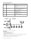
You arrived at this step because you received a “...fanfail...” message or you found a problem with the
switch supervisor control cable (S00-SP-P102).
1. One or more of the following conditions exist:
v Warning Fan: “fanwarning1”, “fanwarning2”, ..., “fanwarning5”
v Shutdown Fan: “fanfail1”, “fanfail2”, ..., “fanfail5”
2. Have customer remove the SP Switch from the active configuration and power off the SP Switch.
3. Set switch circuit breaker to the Off position.
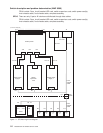
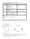
4. Unplug cables connected to J1 and J2 at the rear of the SP Switch.
5. Remove the front panel assembly from the inner chassis.
6. Use Table 1-4 on page 1-8 to reseat or replace components:
SP Switch environment (MAP 0600)
Chapter 1. Maintenance Analysis Procedures (MAPs) 1-7