


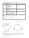
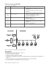

There are two LEDs on the front of each SP Switch. For quick reference, their definitions are as follows:
Environment (Yellow)
Off No environmental problems detected by switch supervisor card.
On Warning of environmental condition out of nominal range. Preventative Maintenance should
be scheduled for this switch.
Flashing
Serious environmental condition detected; power shut off.
Power (Green)
Off No 48 V dc power available at the SP Switch.
Flashing
Power available at the SP Switch, but switch logic is Off.
On Power available at the SP Switch, and logic is On.
Note: Refer to “Service position procedures” on page 3-9 for placing or removing the SP Switch into or
from service position.
Step 0590-001
Read the following warning and then follow steps to ensure continuity of customer’s jobs in the queue.
Attention: Servicing a processor node or SP Switch will interrupt customer usage of the processor node
and the remainder of the switch network. If the switch feature must be replaced in a multi-frame system,
refer to “Removing and restoring switch resources” on page 3-7, for information on isolating the SP Switch.
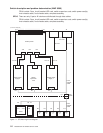
Attention: It is possible that the customer has modified switch cabling from standard configurations;
therefore, be careful about relying on node and frame information. Any connector jack numbers will be
correct regardless of the customer’s cable configuration, so you may trace the cabling from the jack
number if necessary.
1. Have customer complete all active parallel jobs or jobs using switch interface (for example, tape B/U
ADSM), then remove the switch feature from the active configuration. Refer to “Removing and
restoring switch resources” on page 3-7, for these procedures.
2. Check for system monitor errors indicating environmental problems with the switch feature. These can
be viewed by issuing the appropriate command from the control workstation:
v errpt -a -N sphwlog | pg (For SSP code levels 1.02 and higher)
v Refer to the ″Starting a service call (MAP 0100)″ in
RS/6000 SP: System Service Guide
for more
information on the pg command
Note: In a frame with processor nodes, entries for the switch will refer to “node17” or “slot17”. In a
multi-switch frame, switches will be listed as even slot addresses.
3. Determine the SP Switch type (see page 1-1)
4. Refer to Table 1-1 on page 1-4 for a prioritized list of conditions. Find the first condition that describes
your problem, then perform the associated action.
Switch description and problem determination (MAP 0590)
Chapter 1. Maintenance Analysis Procedures (MAPs) 1-3