


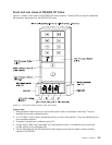
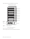
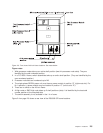
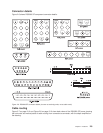
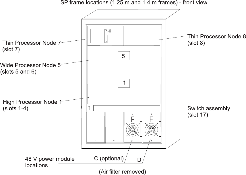
Figure notes:
1. Wide processor nodes take up an entire shelf position (two thin processor node slots). They are
identified by the odd numbered position.
2. In a F/C 2030/1 frame, switch assemblies take up an entire shelf partition. (They are identified by the
even-numbered position.)
3. Processor node slots are numbered up to N8.
4. The single-phase SEPBU power unit must have a power module in position “D” (right-most slot). For
N+1 operation, a power module may be installed in position “C” (next to slot “D”).
5. There are no skirts on the 49-inch frame.
6. A High node or SMP High node takes up 2 shelf positions (slots). It is identified by the least odd
number position of the occupied slots.
7. The switch assembly is not available in the 1.4 m frame.
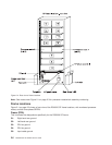
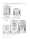
Figure 2-4 on page 2-6 shows a rear view of the RS/6000 SP frame locations.
Figure 2-3. Front view of 49-inch frame locations. See notes below.
Chapter 2. Locations 2-5