


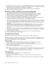
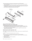

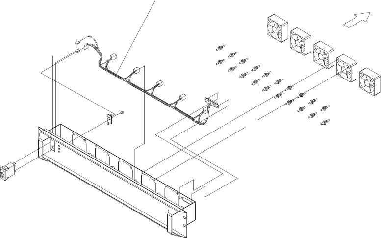
Perform these procedures to remove the fan control cable from an SP Switch assembly:
1. Perform “Placing a switch assembly into service position” on page 3-9 to place the switch assembly
into the service position.
2. Unplug connectors P7, P8 and P9. Remove cable by unhooking retaining material along raceway, and
unplugging the Fan connectors P2, P3, P4, P5 and P6. Using fingertip pressure, remove connector P1
by removing screws. Retain these screws for new cable installation.
3. Remove cable by unhooking retaining material along raceway.
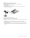
Replacing the switch front chassis cable
Perform these procedures to replace the fan control cable in an SP Switch assembly:
1. Using fingertip pressure attach connector P1 with screws retained in the removal procedure. Route
cable along raceway, hooking retaining material where needed and plugging Fan connectors P2, P3,
P4, P5 and P6. Plug connectors P7, P8 and P9.
2. Perform “Replacing a switch assembly from service position” on page 3-9 to remove the switch
assembly from the service position.
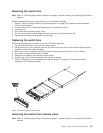
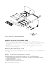
Removing the switch supervisor card
Note: Refer to “Handling static-sensitive devices” on page 4-1 before removing or installing ESD sensitive
devices.
Attention: The hexhead retaining screws requirea4mmsocket.
Perform these procedures to remove the supervisor card from an SP Switch assembly:
1. Perform “Placing a switch assembly into service position” on page 3-9 to place the switch assembly
into the service position.
2. Unplug connector P5.
3. Rotate card thumb locks outward to unseat card.
4. Remove supervisor card.
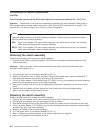
Switch front
chassis cable
Air flow
5
4
3
2
1
Figure 4-3. Removing the SP Switch fan control cable
4-4 RS/6000 SP: SP Switch Service Guide