


Chapter 2. Locations
Naming standard for RS/6000 SP components .....................2-1
Format structure ...............................2-1
Example of format structure ..........................2-1
Frame (WWW) ...............................2-1
Major assembly (XXX) ............................2-2
Sub-assembly (YY) .............................2-2
Connection location (ZZZZ) ..........................2-2
Examples for using complete levels of nomenclature .................2-2
Location diagrams of the RS/6000 SP components ....................2-2
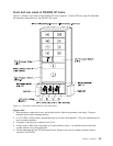
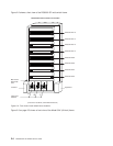
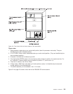
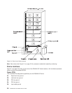
Front and rear views of RS/6000 SP frame......................2-3
Frame locations ................................2-6
Frame (FRA) ................................2-6
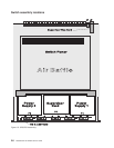
Switch assembly locations ............................2-8
Connector details ...............................2-9
Cable routing.................................2-9
Cable routing in a multi-switch frame (F/C 2030/1)...................2-11
Switch data cables ..............................2-13
SPS data cables ..............................2-13
SPS-8 data cables .............................2-13
Naming standard for RS/6000 SP components
The purpose of this section is to define a naming standard for all components in the RS/6000 SP system.
This standard provides a consistent, logical naming convention system necessary for documentation
including details, assembly drawings, schematics, manufacturing documents, service documents, and
customer publications.
Format structure
The RS/6000 SP system is structured in a modular fashion with different levels of assembly which can be
independently described. These levels are:
1. System level
2. Frame level
3. Major assembly level (e.g. processor node).
4. Sub-Assembly level (e.g. cards, fan assembly).
The format structure is used to individually identify any connection location at any level in the assembly.
The main use of this format is to describe connector, cabling, and schematic locations shown in tables and
diagrams throughout this manual.
Example of format structure
Format: FRAME(WWW) - MAJOR ASSEMBLY(XXX) - SUBASSEMBLY(YY) - CONNECTOR NUMBER (ZZZZ)
Frame (WWW)
v 1st character is the frame type:
– E for RS/6000 SP frame
– L for logical RS/6000 SP frame (used for models 30X and 40X)
– S for multi-switch frame
– C for control workstation
– Z for another frame such as a server
v 2nd and 3rd characters are the frame number:
– 00 for any/all frames (designates location inside any/all frames)
© Copyright IBM Corp. 1999, 2002 2-1