


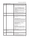
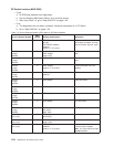
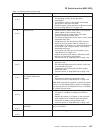

Table 1-10. Switch problem priority listing
Priority Failing component Action
1
(1 of 7)
Software a. Have customer verify that the software is configured
and operating correctly for this processor
node/system.
b. If no problem is found, continue with next highest
priority item in the list for this SRN.
c. Otherwise, power off this processor node and continue
service at “Step 0620-017” on page 1-28.
2
(2 of 7)
External clock a. Check to see if a switch clock cable is connected at
switch adapter of this processor node.
b. If clock cable exists, reseat switch clock cable;
otherwise reseat switch data cable.
c. Run advanced diagnostics on the device “css0” and its
associated switch port.
d. If diagnostics fail with the previous SRN, check at
least one other processor node for indication of a
clock problem. If necessary, run advanced diagnostics
on this other node, using the device “css0” and its
associated switch port.
e. If more than one node has a clock problem, go to
“Step 0620-013” on page 1-28.
f. Replace the switch clock cable or switch data cable
that was just reseated in step 2 above.
g. Continue service at “Step 0620-018” on page 1-28.
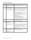
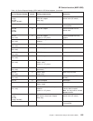
3
(3 of 7)
Data cable a. Reseat switch data cable at switch adapter of this
processor node.
b. Run advanced diagnostics on the device “css0” and
its associated switch port.
c. If diagnostics fail with the previous SRN, replace
switch data cable.
d. Continue service at “Step 0620-018” on page 1-28.
4
(4 of 7)
SPS Adapter
SP System Attachment
Adapter
a. Replace the switch adapter card on this processor
node.
b. Reconnect all cables to the processor node.
c. Continue service at “Step 0620-018” on page 1-28.
Note: Before disconnecting cables or performing service
actions on an SP-Attached Server, perform ″Decoupling
and coupling code for SP-Attached Servers″ in
RS/6000
SP: System Service Guide
.
5
(5 of 7)
System or I/O planar a. Run advanced diagnostics on the “Base System” or
I/O planar. If a problem is detected, use SRN to
service.
b. Replace the system or I/O planar on this processor
node. Make sure to reinstall all parts and cables.
c. Reconnect all cables to the processor node.
d. Continue service at “Step 0620-018” on page 1-28.
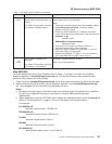
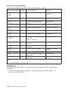
6
(6 of 7)
Wrap plug or
Terminator
Check the wrap plug or terminator again to make sure
that it is not at fault.
7
(7 of 7)
All components replaced. Call next level of support.
SP Switch function (MAP 0620)
Chapter 1. Maintenance Analysis Procedures (MAPs) 1-27