


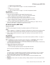
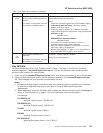
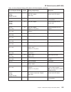
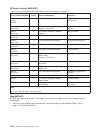

Table 1-7. SP Switch error conditions (continued)
Error # Message/condition Description and action
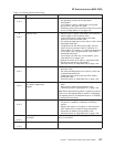
−8
(SPS)
Device status: Device has been
removed from network because of a
miswire
Link status: Link has been removed
from network, probable miswire
Description: Initialization of this link detected a different switch
node number than the one expected.
Action:
1. Check this connection against the actual hardware cabling.
2. If the cabling does not match, correct the cabling
problem, then go to step 5.
3. Check the node’s hostname (or IP address) and switch
node number against the configuration using the command:
splstdata -s | pg
(standard node)
SDRGetObjects DependentAdapter
(dependent node)
4. If this occurs on all nodes of a frame, check for a
logical-to-physical frame number mismatch.
5. Have the customer update the configuration, or you can
correct the cabling, as appropriate.
6. Repeat “Step 0620-001” on page 1-17 for next problem or
go to “Step 0620-043” on page 1-36 to verify fix.
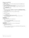
−9
(SPS)
Device status: Destination not
reachable
Link status: Link has been removed
from network, not connected
Description: Possible hardware problem.
Action: Go to “Step 0620-004”.
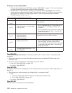
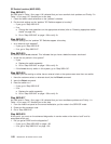
Step 0620-004
You were directed here by an Error Condition listed in Table 1-7 on page 1-19 which lists functional
problems reported in /var/adm/SPlogs/css/out.top file. This file lists all switch data connections with
comment lines indicating the various types.
1. Check the entire /var/adm/SPlogs/css/out.top file for errors before proceeding to the prioritized table.
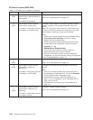
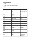
2. Use the following prioritized table to service problems reported in the /var/adm/SPlogs/css/out.top
file. The messages are from comment lines preceding the error.
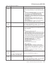
Notes:
a. Be aware that wrap plugs or terminators used in the following steps can potentially fail; therefore,
be sure that a diagnostic wrap plug or terminator is not faulty before performing major
replacements.
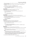
b. Where applicable, frame and SP Switch jack numbers are indicated on each line of the out.top file.
(Refer to “Format structure” on page 2-1 for more information on the nomenclature.)
For example:
L01-S00-BH-J18
identifies Logical frame 1, S00-BH-J18
E02-S00-BH-J18
identifies Physical frame 2, S00-BH-J18
L03-N01
identifies Logical frame 3, Node 1
E02-N04
identifies Physical frame 2, Node 4
S01-S02-BH-J3
identifies Multi-switch frame 1, slot 2, BH-J3
SP Switch function (MAP 0620)
Chapter 1. Maintenance Analysis Procedures (MAPs) 1-21