


v If yes:
a. Have the customer remove the SP Switch from the active configuration and power off the SP
Switch.
b. Go to “Step 0610-010”.
v If no:
a. Fix any cable connection problems.
b. Return to “Step 0610-006” on page 1-15.
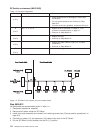
Step 0610-010
You have an SP type switch that is either tripping the circuit breaker to the Off position or the circuit
breaker is on but the Power (green) LED is not lit.
1. Turn off the circuit breaker.
2. Unplug cables connected to J1 and J2 at rear of the SP Switch.
3. Remove the front panel assembly from the inner chassis.
4. Unplug inner chassis cable from the switch power cards S00-PC-P4, S00-PC-P6 and the switch
supervisor card S00-SP-P5.
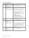
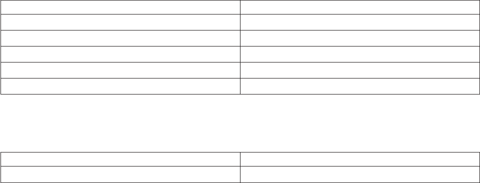
5. Using a digital multimeter, check for inner chassis cable continuity from the switch tailgate and the
connectors in Table 1-5:
Table 1-5. Inner chassis cable continuity
From To
S00-BH_J1 pin 5&9 P6 pin 2
S00-BH-J1 pin 5&9 P4 pin 2
S00-BH-J1 pin 1&6 P3 pin 16
P3 pin 17 p6 pin 1
P3 pin 17 p4 pin 1
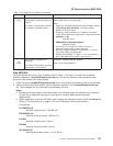
6. On the fan assembly, with circuit breaker in the On (‘1’) position, check for front chassis cable
continuity between the connectors in Table 1-6:
Table 1-6. Front chassis cable continuity
From To
P1 pin 17 P1 pin 16
7. Is there continuity?
v If you have continuity on all cables, go to “Step 0610-013” on page 1-17.
v If you do not have continuity on an inner chassis cable, go to “Step 0610-011”.
v If you do not have continuity on an front chassis cable, go to “Step 0610-012”.
Step 0610-011
An inner chassis cable failed the continuity test.
1. Replace inner chassis cable.
2. Return to “Step 0610-004” on page 1-14 to verify the replacement cable.
Step 0610-012
An front chassis cable failed the continuity test.
1. Ensure that the circuit breaker is in the On (‘1’) position.
2. Check for continuity between the tabs of the circuit breaker.
3. Is there continuity?
v If yes:
SP Switch power (MAP 0610)
1-16
RS/6000 SP: SP Switch Service Guide