


2. Remove the switch supervisor card (refer to “Removing the switch supervisor card” on page 4-4).
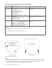
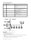
3. Using a digital multimeter, measure resistance at the planar connection for the supervisor card,
between pins 12A and 12B.
v The resistance should be in a range of 4 to 20 ohms.
4. Is the measured resistance in the acceptable range?
v If yes:
a. Replace supervisor card as described in “Replacing the switch supervisor card” on page 4-5.
b. Go to “Step 0600-017” on page 1-10.
v If no, go to “Step 0600-021”.
Step 0600-021
With connectors S00-PC-P4, S00-PC-P6 disconnected, the measured resistance between pins 12A and
12B is outside the specified range.
1. Remove power supply card PS1 (refer to “Removing the switch power cards” on page 4-6.
2. Repeat the resistance measurement from “Step 0600-020” on page 1-10.
3. Is the measured resistance in the acceptable range?
v If yes:
a. Replace the power supply card (refer to “Replacing the switch power cards” on page 4-7.
b. Go to “Step 0600-017” on page 1-10.
v If no, go to “Step 0600-022”.
Step 0600-022
Connectors S00-PC-P4 and S00-PC-P6 are disconnected and you removed power supply card PS1 but
the measured resistance between pins 12A and 12B is still outside the specified range.
1. If this is the first time through this step:
a. Remove power supply card PS2
b. Go to “Step 0600-020” on page 1-10 and repeat the resistance measurement
2. If you have already been through this step:
a. Replace the switch assembly. Go to “Step 0600-017” on page 1-10.
Step 0600-023
You arrived at this location from “Step 0600-018” on page 1-10 where you found a condition state reporting
a PSxFail or PSxFuseGood problem.
1. If you have a PSFuseGood problem, go to “Step 0600-027” on page 1-12.
2. If you have a PS1Fail problem, go to “Step 0600-025” on page 1-12.
3. If you have a PS2Fail problem, go to “Step 0600-024”.
Step 0600-024
You have a PS2Fail problem.
1. Replace power supply card PS2.
2. Reinstall the SPS front panel assembly, being careful to align the guide pins on the P1 to the inner
chassis cup guide.
3. Replug the power cable (J1) and supervisor cable (J2) to the rear of the assembly.
4. Put the circuit breaker in the On (‘1’) position.
5. Does the PS2Fail condition still exist?
v If yes, go to “Step 0600-026” on page 1-12.
v If no, go to “Step 0600-017” on page 1-10.
SP Switch environment (MAP 0600)
Chapter 1. Maintenance Analysis Procedures (MAPs) 1-11