


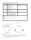

Table 1-4. Fan failure diagnostics
Priority Component Action
1
(1 of 5)
Fan 1, 2, 3, 4 or 5
a. Check specified fans for blockages or loose cable
connections.
b. Fix any obvious problems and continue at “Step
0600-012”.
c. If you do not find any problems, continue at Priority 2.
2
(2 of 5)
Fan 1, 2, 3, 4 or 5
a. Replace fans as described in Chapter 4, “FRU
removals and replacements” on page 4-1.
b. Continue at “Step 0600-012”.
3
(3 of 5)
Switch supervisor card
a. Replace the card.
b. Continue at “Step 0600-012”.
4
(4 of 5)
Switch supervisor control cable
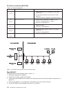
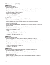
a. Replace the cable. Refer to Figure 1-3, for cable
connections.
b. Continue at “Step 0600-012”.
5
(5 of 5)
All replaced Call next level of support.
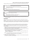
Step 0600-012
You performed the recommended action in Table 1-4.
1. Component replaced or reseated.
2. Reconnect all cables inside the SP Switch.
3. Install front panel assembly and reinstall front retaining screws (see “Service position procedures” on
page 3-9).
4. Connect only power (J1) and supervisor (J2) cables at the rear of the SP Switch.
5. Put the SP Switch’s circuit breaker into the On (‘1’) position.
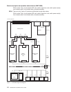
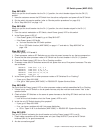
P2 (Fan 1)
2 x 2
P6 (Power Card)
2 x 1
P4 (Power Card)
2 x 1
Front Chassis CableInner Chassis Cable
P5
(Switch SV Card)
2 x 20
P1P3
P3 (Fan 2)
2 x 2
P4 (Fan 3)
2 x 2
P5 (Fan 4)
2 x 2
P6 (Fan 5)
2 x 2
P7, P8 (CB) P9 (LED)
Figure 1-3. SP Switch inner chassis and front chassis cables
SP Switch environment (MAP 0600)
1-8
RS/6000 SP: SP Switch Service Guide