


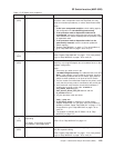
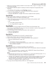
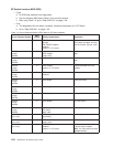
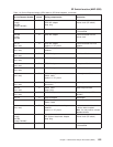
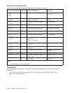

Table 1-7. SP Switch error conditions
Error # Message/condition Description and action
2
(SPS)
Initialized Description: Initialization detected a wrapped port where a
processor node or dependent node was expected (this may
result from isolation procedures), or else a disconnected cable.
Action:
1. If this is an unexpected condition, check cabling against
the configuration file var/adm/SPlogs/css/out.top.
2. If the processor node or dependent node can be
reconnected, remove the wrap plug and connect the data
cable between the switch assembly and the processor node
or dependent node.
3. If the processor node or dependent node is to be
permanently removed, have the customer update the
switch topology.
4. Repeat “Step 0620-001” on page 1-17 for next problem or
go to “Step 0620-043” on page 1-36 to verify fix.
1
(SPS)
Link status: Operational Description: Link status is operational.
Action: Repeat “Step 0620-001” on page 1-17 for next problem
or go to “Step 0620-043” on page 1-36 to verify fix.
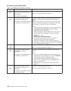
0
(SPS)
Uninitialized Description: Switch adapter has not been initialized. Processor
node may not recognize adapter due to hardware failure or bad
software configuration.
Action:
1. If there are any other errors in the
/var/adm/SPlogs/css/out.top file, address those errors first.
Note: If the problem is on all nodes in the frame, check for
any hardware problems with the SP Switch. Also check for
switch-to-switch problems on all jacks of the SP Switch.
2. If all the nodes are uninitialized except for the primary node,
verify that the primary node is connected to the correct port.
3. Have customer verify that the correct switch software is
installed and running on this node. rc.switch or
css_restart_node starts the
fault_service_Worm_RTG_SP daemon and the
fs_monitor daemon.
4. Log into processor node and enter:
lscfg | grep css
5. If you get no result, try swapping in another switch
adapter. Repeat step 3. If you get a result, the problem is
probably resolved; repeat “Step 0620-001” on page 1-17 for
next problem or go to “Step 0620-043” on page 1-36 to
verify fix.
6. The problem is probably the SP Switch. Go to “Step
0620-004” on page 1-21.
−1
(SPS)
Device status: Device not
responding
Link status: Link as been removed
from network, other stage faulty
Description: Possible hardware problem.
Action: Go to “Step 0620-004” on page 1-21.
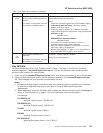
−2
(SPS)
Link status: Wrap plug is installed Description: Initialization detected a wrap plug or cable rather
than the expected cabling.
Action: Repeat “Step 0620-001” on page 1-17 for next problem
or go to “Step 0620-043” on page 1-36 to verify fix.
SP Switch function (MAP 0620)
Chapter 1. Maintenance Analysis Procedures (MAPs) 1-19