


Step 0600-004
Perspectives indicated a shutdown condition and Table 1-2 on page 1-5 directed you to this step.
1. One or more of the following conditions exist:
v Voltage out of range: +5 V “shutdownP5”
v Voltage out of range: +12 V “shutdownP12”
v Voltage out of range: −5 V “shutdownN5”
2. Have the customer remove the SP Switch from the active configuration and power off the SP Switch.
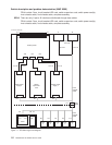
3. Put the switch into service position. Refer to “Service position procedures” on page 3-9.
4. Check the following hardware items:
v Cable conditions at switch supervisor card S00-SP-J102
v Cable conditions at power supply S00-PC-P4 and S00-PC-P6.
v Cable conditions of wires, especially the inner chassis cable.
5. Leave the cable disconnected at the switch power card.
6. Does the switch supervisor control cable appear to be okay?
v If yes, go to “Step 0600-005”.
v If the switch supervisor control cable (S00-SP-P102) appears to have a problem, go to “Step
0600-011” on page 1-7. Refer to Priority 4 and replace the cable.
Step 0600-005
After placing the switch into the service position, you performed some basic inspections and found that the
switch supervisor control cable (S00-SP-P102) appears to be okay.
1. Disconnect S00-PC-P4 and S00-PC-P4 at the power supply.
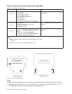
2. Using a digital multimeter, measure resistance between the appropriate pins.
3. Compare results with values in Table 1-3:
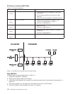
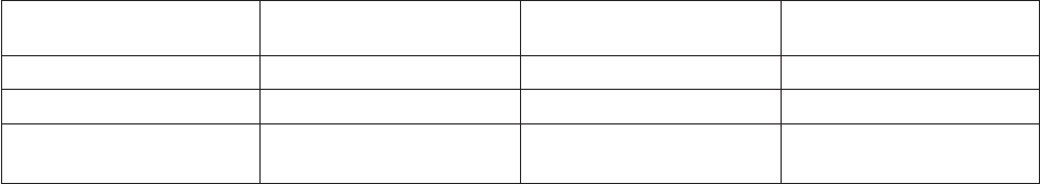
Table 1-3. Switch connector resistance values
Voltage
Measure from
(positive lead)
To GND
(negative lead)
Acceptable range
(in ohms)
+5 V Pin 1 Pin 2 (black) 1K - 5M
+12 V Pin 3 Pin 2 (black) 1K - 5M
−5 V Pin 5
Pin 7
Pin 2 (black)
Pin 2 (black)
2-20
2-20
4. Is the measured resistance in the acceptable range?
v If yes, go to “Step 0600-009” on page 1-7.
v If no, go to “Step 0600-006”.
Step 0600-006
The resistance value you measured in Table 1-3 was not within an acceptable range.
1. Replace the inner chassis cable.
2. Repeat resistance measurement from “Step 0600-005”.
3. Is the measured resistance in the acceptable range?
v If yes, go to “Step 0600-017” on page 1-10 to verify fix.
v If no, go to “Step 0600-007”.
Step 0600-007
You disconnected S00-CL-P5 at the switch clock card but the measured resistance was still outside the
acceptable range.
1. Replace the front chassis cable.
2. Repeat resistance measurement from “Step 0600-005”.
SP Switch environment (MAP 0600)
1-6
RS/6000 SP: SP Switch Service Guide