


6. The customer can re-initialize the switch using the Estart command. The frame and processor nodes
which were removed in this procedure will appear in the out.top file with error messages; however, the
remainder of the switch resources are now available for customer use.
7. If switch re-initialization was successful, the customer can start running parallel jobs again.
8. Return to MAPs to continue service action(s).
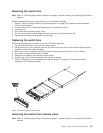
Restoring a switch assembly to the active configuration
1. Identify the switch assembly which is to be restored to the active configuration.
2. Have customer stop all current parallel jobs and suspend all parallel jobs on the job queue.
3. Make sure that the circuit breaker at the front of the switch assembly in the Off (‘0’) position.
4. Connect all cables to the switch assembly. Pay attention to the labels on the cables.
5. Put the circuit breaker at the front of the switch assembly in the On (‘1’) position.
6. Use switch front panel or the Eclock command to select the appropriate clock input for this switch
assembly. For SSP code level 1.02 and higher, use the Eclock -r command.
7. If the primary processor node was changed during the isolation procedure, the customer can change
the primary processor node back to the original selection; however, this is NOT required. The primary
node is set by the Eprimary command. Refer to
IBM RS/6000 SP: Administration Guide
, for more
information.
8. If the master clock was changed during the isolation procedure, the customer can select the
clocks on all other switches; however, this is not suggested. (The previous clock selection for this
switch assembly was recorded for possible use. See “Selecting appropriate switch clocks” on
page 3-6.)
9. The customer can re-initialize the switch using the Estart command. Cables connected to the switch
assembly and processor nodes which were restored in this procedure should appear in the out.top
file without any error messages.
10. If switch re-initialization was successful, the customer can start running parallel jobs again.
11. Return to MAPs to continue service action(s).
Viewing switch partitions
Open the System Monitor window and click on the “View“ option to display any partitions.
With switch partitioning, the nodes are grouped under a partition name. Partitioning allows the SP to have
different software levels installed, and to isolate groups of nodes from each other. The Estart command,
fault service, and applications see only a single partition.
Fencing nodes
1. Click on “View” to select one of the partitions, then click on “SP” to display an options menu.
2. Click on “Global Controls” to display the frame(s) and node(s) in this partition.
3. Click on the node you want to fence, then click on the “Shutdown” option. Now click on the “Do
Command” option to display options.
4. Click on “Fence” and then click on “Shutdown” to shutdown the node.
Note: Selecting “Enable Autojoin” during this sequence will automatically place the node back into the
operations of the partition on successful power on of the Node. It is suggested that “Autojoin”
not
be selected at any time when performing a service action.
Unfencing nodes
1. If necessary, follow the first 2 steps under “Fencing Nodes” above.
2. Ensure that the node is selected.
3. Click on “On” and then click on “Do Command”. This will power on the node and run power-on
diagnostics.
4. Click on “Unfence” and then click on “Do Command” to place the node into operation in the partition.
3-8 RS/6000 SP: SP Switch Service Guide