


Efence of primary and primary backup nodes
By design, Efence of primary and primary backup nodes is not allowed.
If you attempt to fence either of these nodes, you will get the following responses:
Efence: 0028-147 Node number designates the Primary Node.
Efence: 0028-166 Node number designates the Primary Backup Node.
You should assign a new primary or primary backup node and initiate a restart to be able to remove
these nodes from the network for service.
Service position procedures
Note: When preparing to place processor node(s) and/or switch assembly(s) into service position, ensure
that the customer has removed the processor node(s) and/or switch assembly(s) from the active
configuration.
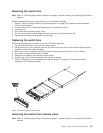
Placing a switch assembly into service position
1. Set circuit breaker in the Off (‘0’) position.
2. Remove power (J1) and supervisor (J2) cables from rear of switch assembly.
3. Remove the four screws from the front of the switch assembly.
4. Remove the SPS front panel assembly from the inner chassis by pulling at the side of the front panel
assembly.
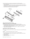
5. If the inner chassis or supervisor power cable need to be replaced:
a. Detach all cables from the rear of the switch assembly, noting where the external frame cables and
wrap plugs are attached.
b. Remove the inner chassis from the outer chassis sleeve by pushing on the inner chassis from the
rear of the switch assembly.
Replacing a switch assembly from service position
1. If the inner chassis or supervisor power cable needed to be replaced:
a. Replace the inner chassis into the outer chassis sleeve.
b. Reattach all cables to the rear of the switch assembly.
2. Reinstall the SPS front panel assembly into the inner chassis, being careful to align the guide pins of
the P1 connector to the inner chassis weld. Then apply light even pressure at the sides of the front
panel assembly.
3. Reinstall the four screws into the front of the switch assembly.
4. Reattach power (J1) and supervisor (J2) cables to the rear of switch assembly.
5. Set circuit breaker in the On (‘1’) position.
Resetting the clock and bootlist after servicing a node
When servicing a node, the node becomes disconnected from its power source for a period of time. Since
nodes normally do not have a real battery, the NVRAM will loose it’s memory when disconnected from
power for about 10 minutes (sometimes less). This will cause the date to be reset to January 1, 1970, and
the bootlist to be cleared. This can cause some problems with booting.
It is highly recommended to reset the clock and bootlist before booting the node. This is done as follows:
1. Before powering down the node to be serviced, display the current bootlist:
a. Run diagnostics (diag)
b. Choose the “Service Aids” panel
c. Choose the “Display/Alter Bootlist” panel
Chapter 3. Service procedures 3-9