


Note: See notes under Figure 2-1 on page 2-3 for processor node/switch assembly numbering.
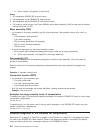
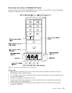
Frame locations
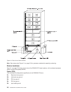
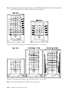
Figure 2-1 on page 2-3 shows a front view of the RS/6000 SP frame locations, with numbered processor
nodes, and the three phase SEPBU.
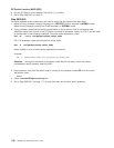
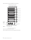
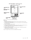
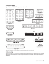
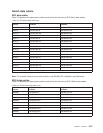
Frame (FRA)
This list shows the designations specifically for the RS/6000 SP frame:
G1: Right-hand rear ground
G2: Left-hand rear ground
G3: PDU ac ground
G4: PDU dc ground
G5: Input cable ground
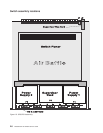
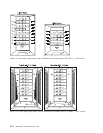
Figure 2-4. Rear view of frame locations
2-6 RS/6000 SP: SP Switch Service Guide