


Chapter 1. Maintenance Analysis Procedures (MAPs)
This chapter provides information for identifying problems and guides you to the most likely failed Field
Replaceable Unit (FRU). The MAPs then refer you to the FRU Removal/Replacement procedures for the
corrective action.
v “SP Switch description and problem determination (MAP 0590)”
v “SP Switch environment (MAP 0600)” on page 1-5
v “SP Switch power (MAP 0610)” on page 1-13
v “SP Switch function (MAP 0620)” on page 1-17
SP Switch MAPs
SP Switch description and problem determination (MAP 0590)
Purpose of this MAP
This MAP describes the physical characteristics of each switch type and provides a table (Table 1-1 on
page 1-4) containing diagnostic information.
Each switch network has the following components:
v Switch adapter cards (one per processor node)
v SP Switch
v Switch internal data cables
v Switch power cable
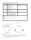
v Switch wrap plugs (male 77G0818 and female 46H9688 for SPS). Refer to Figure 1-2 on page 1-4 for
views of the wrap plug.
v Switch external data cables (multi-frame only)
Attention:
1. Switch data plug/jack connector pins are easily bent. Check for bent pins on male plugs or bent pin
guides on female jacks if a cable is difficult to plug. Problems with bent pins or pin guides can
propagate to new plugs/jacks if not corrected first.
2. All connected SP Switches must be running from the same master clock. If the SP Switches have not
been set properly, all processor nodes in a logical frame will be uninitialized. Refer to “Selecting
appropriate switch clocks” on page 3-6 for these procedures.
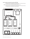
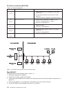
Refer to Figure 1-1 on page 1-2 for a high-level view of the RS/6000 SP Switch.
Switch connection types
Standard node
Processor nodes in 9076 SP frames are attached to the SP Switches with switch cables.
Dependent node
Switch adapter resides outside of the 9076 SP frame. Each dependent node is a single SP
Switch Router Adapter in the 9077 Switch Router. There can be several dependent nodes in
each SP Switch Router.
Switch-to-switch
Connections between SP Switches.
SP Switch types
SPS All clocks are distributed through data cables. External clock inputs are selected from J3, J4,
or J5.
© Copyright IBM Corp. 1999, 2002 1-1