


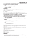
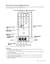

Front and rear views of RS/6000 SP frame
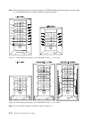
Figure 2-1 shows a front view of the RS/6000 SP frame locations. “Frame (FRA)” on page 2-6 describes
the assembly designations for the RS/6000 SP frame.
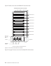
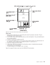
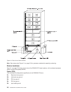
Figure notes:
1. Wide processor nodes take up an entire shelf position (two thin processor node slots). They are
identified by the odd numbered position.
2. In a F/C 2030/1 frame, switch assemblies take up an entire shelf partition. (They are identified by the
even-numbered position.)
3. Processor node slots are numbered up to N16.
4. A High node or SMP High node takes up 2 shelf positions (slots). It is identified by the least odd
number position of the occupied slots.
5. Frames equipped with the SP Redundant Power Supply must have four power modules (books)
installed in the SEPBU.
Figure 2-1. Front view of frame locations. See notes below.
Chapter 2. Locations 2-3