


1 Input 1 (BH-J3 for SPS)
2 Input 2 (BH-J4 for SPS)
3 Input 3 (BH-J5 for SPS)
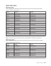
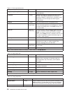
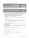
Table 3-4. Setting switch clock sources
Model
Number of Logical
Frames
Master Clock Choice
123
30x 1-4 L01-S00 = i
L02-S00 = 1
L03-S00 = 1
L04-S00 = 1
L01-S00 = 1
L02-S00 = i
L03-S00 = 2
L04-S00 = 2
L01-S00 = 2
L02-S00 = 2
L03-S00 = i
L04-S00 = 3
30x 5 L01-S00 = i
L02-S00 = 1
L03-S00 = 1
L04-S00 = 1
L05-S00 = 2
L01-S00 = 1
L02-S00 = i
L03-S00 = 3
L04-S00 = 2
L05-S00 = 2
L01-S00 = 2
L02-S00 = 3
L03-S00 = i
L04-S00 = 3
L05-S00 = 3
40x 4-8 S01-S02=i
All others = 1
S01-S06=i
All others = 2
S01-S10=i
All others = 3
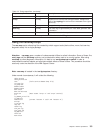
Note: On an 8-port switch, the clock always equals 0. See samples in /etc/SP.
Removing and restoring switch resources
This procedure can be performed to allow customer to use a switch feature while extended service actions
are performed on an individual frame of a multi-frame system with the switch feature.
DO NOT PERFORM this procedure unless the required service operation will take the switch out of the
switch configuration for a minimum of two hours (for example, a part must be ordered or a switch
assembly or frame must be repeatedly powered on/off) and/or the customer specifically requests it.
Care should be taken to understand the consequences on any partitions that might be sharing switch
resources. See “Viewing switch partitions” on page 3-8.
Attention: This procedure is intended to allow the customer to use the switch feature during extended
repair action. The customer must stop all parallel jobs prior to starting the repair. Once the repair is
complete, the customer must stop all parallel jobs again to reconfigure the switch to include the resource
again. If the service action is expected to be complete in a short period of time (for example, two hours or
less), this additional interruption of all parallel jobs will probably cost the customer more time than was
saved by use of the switch feature during that short period.
Removing a switch assembly from the active configuration
1. Identify the switch which is to be removed from the active configuration for an extended period of time.
Display the clock selection for this switch assembly and record it for later use. See “Selecting
appropriate switch clocks” on page 3-6.
2. If the primary processor node (usually in Frame 1) is connected to the switch identified in step
1, the customer must select an available processor node to be the new primary processor node. The
primary node is set by the Eprimary command. Refer to
IBM RS/6000 SP: Administration Guide
for
more information.
3. If the master clock selected for the switch is from the switch assembly identified in Step 1, the
customer must select a new master clock. Refer to “Selecting appropriate switch clocks” on page 3-6.
4. Have customer stop all current parallel jobs and suspend all parallel jobs on the job queue.
5. Put circuit breaker at the front of switch assembly in the Off (‘0’) position.
Chapter 3. Service procedures 3-7