


EonStor A16E-G2130-4 Installation and Hardware Reference Manual
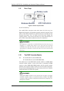
The controller board is housed in a metal canister and is referred to as the
“controller module.” The controller module is comprised of a main circuit
board, an interface faceplate, and a metal canister. The controller module is
accessed through the rear of the A16E-G2130-4 with the help of ejection
levers. An optional battery backup unit (BBU) is now equipped with an
EEPROM that helps record the installation date and notify system
administrators if the battery’s life expectancy is reached. The BBU is hot
swappable and is accessed through the controller’s faceplate.
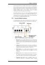
Four (4) RJ-45 connectors connect the subsystem to network switches or
Ethernet ports of independent devices. Dual-redundant, hot-swappable
cooling modules and power supplies protect the subsystem from overheating
and the down time by power outage. The modular nature of the subsystem
and the easy accessibility to all major components ensure the ease of the
subsystem maintenance.
NOTE:
On receiving and unpacking your subsystem, please check the package
contents against the included Unpacking Checklist. If any modules are
missing, please contact your vendor immediately.
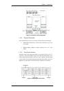
1.1.2 Enclosure Chassis
1.1.2.1 Chassis Overview
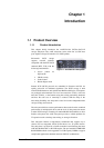
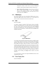
The A16E-G2130-4 RAID storage is housed in a 3U metal chassis that is
divided into front and rear sections. Key components are respectively
accessed through the front (see Figure 1-3) and rear (see
Figure 1-4)
panels. The enclosure chassis can be mounted into a standard 19-inch rack
or enclosure cabinet using support brackets that are separately-purchased.
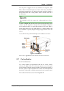
NOTE:
Components accessed through the front panel are referred to as “Front
Panel Components” and components accessed through the rear panel are
referred to as “Rear Panel Components.”
Product Overview
1-2