


EonStor A16E-G2130-4 Installation and Hardware Reference Manual
event notification via email, fax, LAN broadcast, SNMP traps,
MSN Messenger, SMS (Short Message Service), and the
configuration utility screen. The Configuration Client helps
prevent blind time and keeps you constantly informed of the status
of the subsystem. Instructions on how to activate the
Configuration Client functionality are given in the RAIDWatch
User’s Manual.
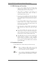
LEDs: Device-status-indicating LEDs are located on all important
modules. These LEDs inform you of the integrity of a given
component or a host/management link. You should become
familiar with the various LEDs and be aware of their functions.
(See Section 3.2)
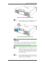
Audible alarm: An audible alarm is present on the subsystem
controller board and will be triggered if any of a number of
threatening events occurred. These events usually jeopardize the
functional and operational integrity of the controller board and
must be heeded at all times. Events such as a breaching of the
temperature threshold will trigger the alarm. If a subsystem
manager is present, the manager should use the RS-232 terminal
console to determine the cause of the alarm and take appropriate
corrective measures. (See Section 3.3)
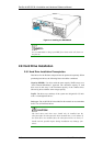
Inter-Integrated Circuit (I
2
C): The I
2
C serial bus is used to
connect various temperature sensors and presence detection
circuits within the chassis.
Subsystem monitoring is a necessary part of subsystem management. If
failure events or other disruptive events are detected and reported, the
subsystem managers must take appropriate actions to rectify the problem.
Failure to act in a properly specified manner to a system event (like
overheating) can cause severe and permanent damage to the subsystem.
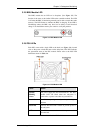
3.2 Status-indicating LEDs
3.2.1 Brief Overview of the LEDs
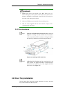
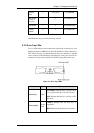
The following devices all come with LEDs that inform subsystem managers
about the operational status of the component.
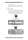
Component LEDs per Unit Total LEDs Definition
Drive Trays
2 32 See Section 3.2.2
Controller
Module
7 7 See Section 3.2.3
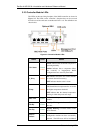
Status-indicating LEDs
3-2