EonStor A16E-G2130-4 Installation and Hardware Reference Manual
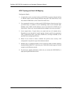
Step 1. Prepare a clean, static-free work pad or container into which to place
the controller that will be removed from the chassis.
Step 2. Make sure there is no data access to the subsystem to avoid losing
data. Stop all I/O accesses to the subsystem and make sure all cached
writes have been distributed to disk drives.
Step 3. Power off the subsystem. If possible, power off the subsystem in the
way described in Chapter 4. Be sure to flush all cached data before
powering off the subsystem. If it is not possible to do this turn off
both PSU modules and disconnect the power cords.
Step 4. Disconnect all cables that are connected to the controller module you
wish to replace. These include the Ethernet cables connected to the
network, and any cable connected to the RS-232C audio jack
connector.
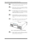
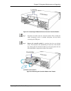
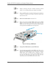
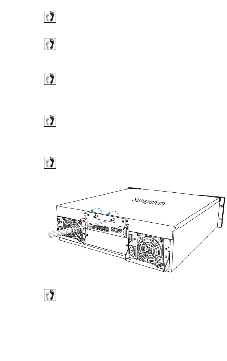
Step 5. Remove the BBU module if one has been installed. Loosen the BBU
module’s retention screws and then retrieve it from the chassis.
Figure
5
5
-1: Loosening the Retention Screws from the BBU Module
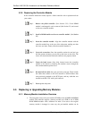
Step 6. Loosen the retention screws from controller. Use a medium-size
Phillips screwdriver to remove the screws underneath each of the
ejection levers. Keep the screws for future use.
5-4 Replacing Controller Module Components


