


EonStor A16E-G2130-4 Installation and Hardware Reference Manual
5.2.4 Replacing the Controller Module
If the controller module has failed, replace a failed controller with a replacement from
your vendor:
Step 1. Remove the failed controller. (See Section 5.2.3) If the DIMM
module is undamaged it can be removed (See Section 5.3) and reused
on the new controller module.
Step 2. Install a DIMM module on the new controller module. (See Section
5.3)
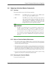
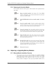
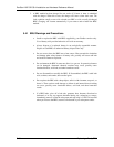
Step 3. Insert the controller module. Align the controller module with the
controller module bay at the rear of the subsystem, making sure that
the levers are down. Gently slide the controller module in.
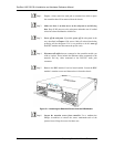
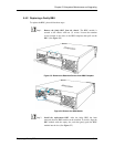
Step 4. Secure the connection. Once the controller reaches the end and you
feel the contact resistance, you can life up the levers on the sides. The
levers will ensure that the back-end connectors are properly mated.
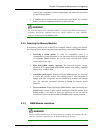
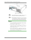
Step 5. Fasten the hand screws. Once fully inserted secure the controller
module to the chassis by fastening the retention screws through the
holes underneath the ejection lever.
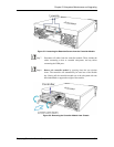
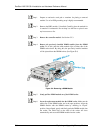
Step 6. Re-attach all the cables that your previously removed. These include
the cables that connect to the local network or iSCSI initiators that
were previously attached to the iSCSI ports, and any cable that was
attached to the RS-232C audio jack connector.
Step 7. Power up the subsystem.
5.3. Replacing or Upgrading Memory Modules
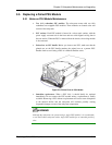
5.3.1 Memory Module Installation Overview
The subsystem comes with a pre-installed 512MB (or above) DDR RAM DIMM
module. The controller supports a memory module up to 2GB in size. If DDR
RAM DIMM modules with a different size need to be used or the original
memory module is damaged in some way, the pre-installed module can be
5-6 Replacing or Upgrading Memory Modules