


Chapter 1: Introduction
The heart of the A16E-G2130-4 RAID controller subsystem is the iSCSI-to-
SATA controller board. The controller comes with four (4) GbE Ethernet
host ports. The subsystem connects to the host through RJ-45 connectors,
while the connectors are also ready to connect to one or more network
switches, enabling access to your storage volumes in complex
configurations such as data-sharing or network zoning.
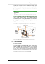
The docking connector at the rear of the controller board connects the
controller module to the backplane board. A DDR RAM DIMM socket is
strategically placed in an easily accessible location on the controller board
for easy insertion of the DDR RAM DIMM module.
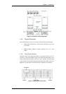
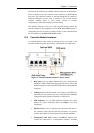
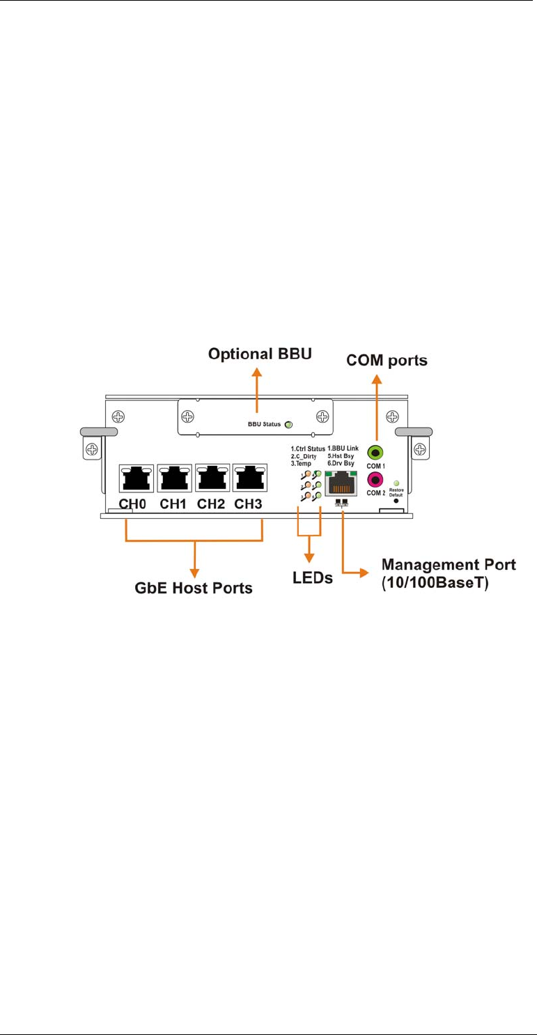
1.2.3 Controller Module Interfaces
All external interfaces that connect to external devices are located on the
controller module rear panel shown below. The interfaces are listed below.
Figure 1-7: Controller Module Interfaces – 2-port version
Host ports: Four (4) Gigabit Ethernet host ports (simulated and
indicated as CH0 to CH3 in the diagram shown above) connect the
EonStor subsystem to the networked iSCSI initiators through RJ-45
connectors.
COM port: The controller module comes with two (2) COM ports.
The serial ports are used for local access to the firmware embedded
configuration utility and the connection to a UPS device.
LED indicators: Six (6) LED indicators illustrate the system
statuses for system monitoring. Please see Chapter 3 for more
information.
Ejection Levers: Two (2) ejection levers located on the sides of
the controller ensure that the back-end connectors are properly
seated in the module slot and properly mated with the backplane.
Management LAN Port: Another 10/100BaseT Ethernet port
connects the subsystem to a management computer. Available
Subsystem Components
1-7