


Chapter 2: Hardware Installation
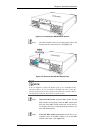
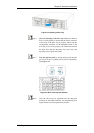
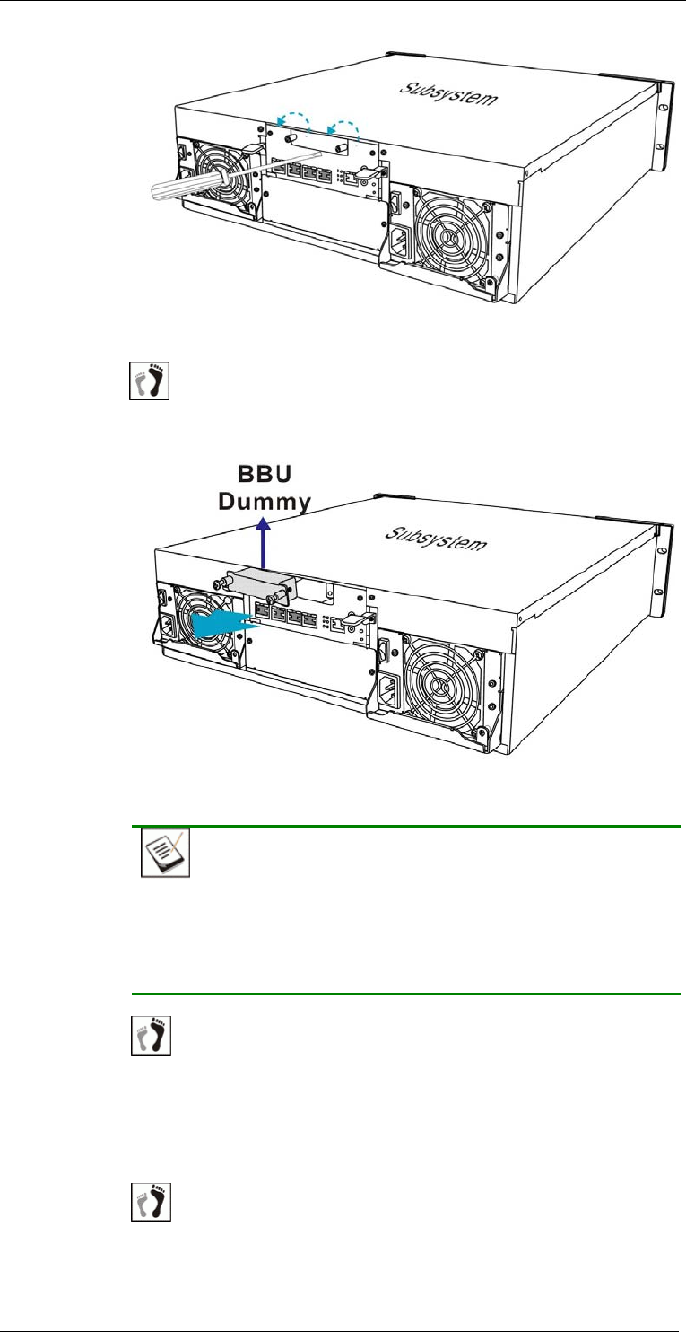
Figure 2-2: Loosening the BBU Retention Screws
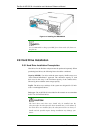
Step 3. Once the retention screws are loosened, gently retrieve the
dummy plate out of the enclosure. (See Figure 2-3)
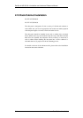
Figure 2-3: Removing the BBU Slot Dummy Plate
NOTE:
It may be difficult to remove the dummy plate as it is embedded in the
subsystem chassis. If you are unable to dislodge the sheet, wedge the
head of a flat-head screwdriver between the metal sheet and the chassis
and then gently nudge the metal sheet out of the chassis.
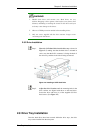
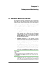
Step 4. Install the BBU module. Align the BBU module with the
BBU module slot and gently insert the BBU module until
the back of the BBU module reaches the end of the slot.
Use slightly more force so that the back-end connector can
mate with the backplane.
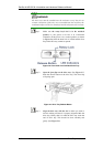
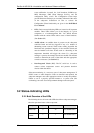
Step 5. Secure the BBU module to the chassis. Fasten the two (2)
retention screws on the BBU module to secure the BBU
module to the chassis. (See Figure 2-4)
BBU Installation
2-9