


Chapter 3: Subsystem Monitoring
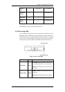
Ethernet
Ports
2 10 (5 ports) See Section 0
BBU Module
(if BBU is
installed)
1 1 See Section 3.2.5
PSU Module
1 2 See Section 3.2.6
Cooling
Module
2 4 See Section 3.2.7
Table 3-1: LED Distribution
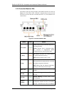
LED definitions are given in the following sections.
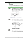
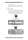
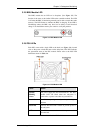
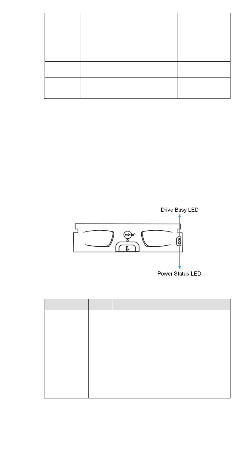
3.2.2 Drive Tray LEDs
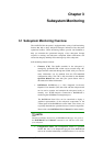
Two (2) LED indicators are located on the right side of each drive tray. (See
Figure 3-1) Refer to Table 3-2 for the LED definitions. When notified by a
drive failure message, you should check the drive tray indicators to find the
correct location of the failed drive. Replacing the wrong drive can fail two
members of a logical array (RAID 3/5) and thus destroy data in the array.
Figure 3-1: Drive Tray LEDs
Name Color Status
Drive Busy
Blue
FLASHING indicates data is being written
to or read from the drive. The drive is busy.
OFF indicates that there is no activity on the
disk drive.
Power Status
Green/
Red
GREEN indicates that the drive bay is
populated.
RED indicates that the disk drive has failed.
Table 3-2: Drive Tray LED Definitions
Status-indicating LEDs
3-3