


Chapter 1: Introduction
The subsystem is equipped with two (2) redundant, hot-swappable, 530W
PSUs, which are installed into the rear section of the chassis. The PSU is
permanently mounted into a 2U (dual-level) bracket especially designed to
house both the PSU and a cooling module, which is mounted at the end of
the 2U bracket.
NOTE:
Hot-swapping the PSU also removes the cooling module at the lower
slot.
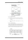
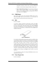
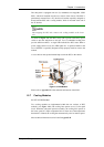
As shown in Figure 1-9, each PSU comes with a power socket and a power
switch to turn the subsystem on and off. Two (2) embedded cooling fans
provide sufficient airflow. A single LED indicates the PSU status. When a
power supply failure occurs, the LED lights red. A rejection handle at the
rear of the PSU is especially designed to help properly install or remove the
module.
A screw hole on the ejection handle helps secure the PSU to the chassis.
Figure 1-9: PSU Module
Please refer to Appendix B for the technical information of the PSUs.
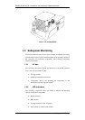
1.2.7 Cooling Modules
PN: IFT-9273ECFanMod
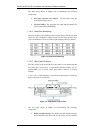
Two cooling modules are implemented within the rear sections of PSU
modules. (see Figure 1-10.) The cooling fans operate at two (2) fan speed
levels. When the subsystem operates normally, the cooling fans operate at
the lower speed. If a major component fails or when one of the temperature
thresholds is violated, the cooling fans automatically raise its rotation speed.
More technical information can be found in Appendix B.
Subsystem Components
1-9