


Chapter 1: Introduction
connectors are on located on the controller’s faceplate. (See
Section 1.2.2)
• BBU module: An optional BBU module sustains unfinished writes
cached in memory during a power outage in order to prevent data
loss. (See Section 1.2.5)
• PSU modules: The hot-swappable PSUs receive single-phase
power and deliver +5V, +12V, and +3.3V power to the subsystem.
A power switch is located on each PSU to turn the system on and
off. (See Section 1.2.6)
• Cooling modules: The redundant cooling modules ventilate the
subsystem to maintain a cooling airflow across the subsystem. (See
Section 1.2.7)
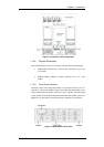
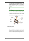
1.1.2.6 Backplane Board
An internal backplane board separates the front and rear sections of the
A16E-G2130-4. The PCB board consists of traces for logic level signals and
low voltage power paths. It contains no user-serviceable components.
WARNING!
When inserting a removable module, DO NOT USE EXCESSIVE
FORCE! Forcing or slamming a module can damage the pins on the
module connectors either on the module itself or on the backplane. Gently
push the module until it reaches the end of module slot. Feel the contact
resistance and use slightly more pressure to ensure the module connectors
are correctly mated. If the module comes with ejection levers or retention
screws, use them to secure the module.
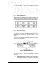
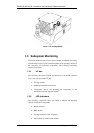
1.2 Subsystem Components
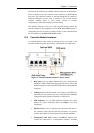
The A16E-G2130-4 houses many active components and most of them can
be accessed through either the front or rear panel. The modular design of the
active components facilitates their easy installation and removal. Hot-swap
mechanisms are incorporated to eliminate power surges and signal glitches
that might occur while removing or installing these modules.
Subsystem Components
1-5