


Datasheet
11
Networkin
g
Silicon —GD82559ER
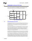
3.5 PHY Si
g
nals
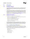
NOTE:
619
Ω
and 549
Ω
for the RBIAS100 and RBIAS10, respectivel
y
, are onl
y
a recommended values and
should be fine tuned for various desi
g
ns.
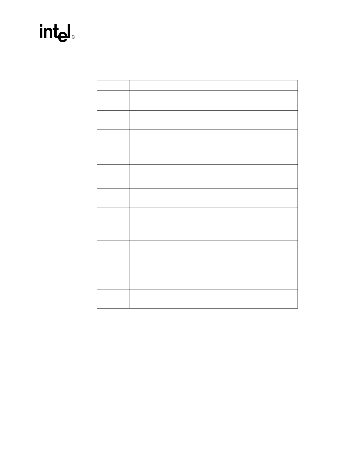
Symbol Type Name and Function
X1 A/I
Crystal Input One.
X1 and X2 can be driven b
y
an external 3.3 V 25
MHz cr
y
stal. Otherwise, X1 ma
y
be driven b
y
an external metal-oxide
semiconductor
(
MOS
)
level 25 MHz oscillator when X2 is left floatin
g
.
X2 A/O
Crystal Input Two.
X1 and X2 can be driven b
y
an external 3.3 V 25
MHz cr
y
stal. Otherwise, X1 ma
y
be driven b
y
an external MOS level
25 MHz oscillator when X2 is left floatin
g
.
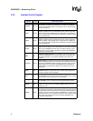
TDP
TDN
A/O
Analog Twisted Pair Ethernet Transmit Differential Pair.
These
pins transmit the serial bit stream for transmission on the Unshielded
Twisted Pair
(
UTP
)
cable. The current-driven differential driver can be
two-level
(
10BASE-T
)
or three-level
(
100BASE-TX
)
si
g
nals dependin
g
on the mode of operation. These si
g
nals interface directl
y
with an
isolation transformer.
RDP
RDN
A/I
Analog Twisted Pair Ethernet Receive Differential Pair.
These pins
receive the serial bit stream from the isolation transformer. The bit
stream can be two-level
(
10BASE-T
)
or three-level
(
100BASE-TX
)
si
g
nals dependin
g
on the mode of operation.
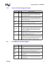
ACTLED# OUT
Activity LED.
The Activit
y
LED pin indicates either transmit or receive
activit
y
. When activit
y
is present, the activit
y
LED is on; when no
activit
y
is present, the activit
y
LED is off.
LILED# OUT
Link Integrity LED.
The Link Inte
g
rit
y
LED pin indicates link inte
g
rit
y
.
If the link is valid in either 10 or 100 Mbps, the LED is on; if link is
invalid, the LED is off.
SPEEDLED# OUT
Speed LED.
The Speed LED pin indicates the speed. The speed LED
will be on at 100 Mbps and off at 10 Mbps.
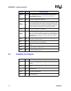
RBIAS100 B
Reference Bias Resistor (100 Mbps).
This pin controls the out
envelope of the 82559ERER when transmittin
g
in the 10 Mbps mode
via the use of a pull-down resistor to
g
round. A value of 619
Ω
pull-
down resistor is ade
q
uate is most applications.
RBIAS10 B
Reference Bias Resistor (10 Mbps).
This pin controls the out
envelope of the 82559ER when transmittin
g
in the 10 Mbps mode via
the use of a pull-down resistor to
g
round. A value of 549
Ω
pull-down
resistor is ade
q
uate is most applications.
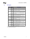
VREF B
Voltage Reference.
This pin is connected to a 1.25 V ± 1% external
volta
g
e reference
g
enerator. To use the internal volta
g
e reference
source, this pin should be left floatin
g
.