


Datasheet
25
Networkin
g
Silicon — GD82559ER
.
4.2.4.6 Auxiliar
y
Power Si
g
nal
The 82559ER senses whether it is connected to the PCI power supply or to an auxiliary power
supply (V
AUX
) via the FLA1/AUXPWR pin. The auxiliary power detection pin (multiplexed with
FLA1) is sampled when the PCI RST# or ALTRST# signals are active. An external pull-up resistor
should be connected to the 82559ER if it is fed by V
AUX
; otherwise, the FLA1/AUXPWR pin
should be left floating. The presence of AUXPWR affects the value reported in the Power
Management Capability Register (PCI Configuration Space, offset DEH). The Power Management
Capability Register is described in more detail in Section 7.1.18, “Power Management Capabilities
Register” on page 54.
4.2.4.7 Alternate Reset Si
g
nal
The 82559ER’s ALTRST# input pin functions as a power-on reset input. Following ALTRST#
being driven low, the 82559ER is initialized to a known state. In systems that support auxiliary
power, this pin should be connected to the auxiliary power’s power stable signal (power good) of
the 82559ER’s power source. In a LAN on Motherboard solution, this signal is available on the
system. In network adapter implementations, an external analog device connected to the auxiliary
power supply can be used to produce this signal. In systems that do not have an auxiliary power
source, the ALTRST# signal should be tied to a pull-up resistor.
4.2.4.7.1 Isolate Si
g
nal
When the 82559ER is connected to V
AUX
, it may be powered on while the PCI bus is powered off.
In this case, the 82559ER isolates itself from the PCI bus. The 82559ER has a dedicated
ISOLATE# pin that should be connected to the PCI power source’s stable power signal (power
good). Whenever the PCI Bus is in the B3 state, the PCI power good signal becomes inactive and
the 82559ER isolates itself from the PCI bus. During this state, the 82559ER ignores all PCI
signals including the RST# and CLK signals. It also tri-states all PCI outputs, except the PME#
signal. In the transition to an active PCI power state (in other words, from B3 power state to B0
power state), the PCI power good signal shifts high.
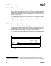
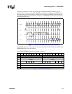
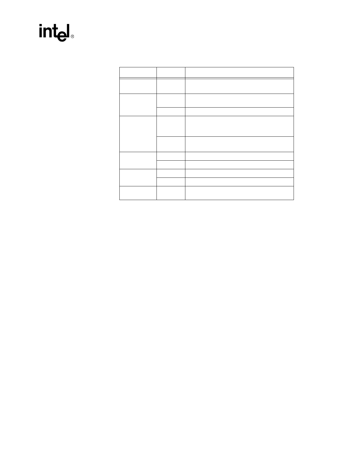
Power State Link 82559ER Functionality
D0u Don’t care
• Power-up state
• PCI slave access
D0a
Valid
Full functionalit
y
at full power and wake on invalid
link
Invalid Full functionalit
y
at full power and wake on valid link
D1
Valid
• Wake-up on “interestin
g
” packets and link
invalid
• PCI confi
g
uration access
Invalid
• Wake on link valid
• PCI confi
g
uration access
D2
Valid Same functionalit
y
as D1
(
link valid
)
Invalid Detection for valid link and no link inte
g
rit
y
D3
(
with power
)
Valid Same functionalit
y
as D1
(
link valid
)
Invalid Detection for valid link and no link inte
g
rit
y
Dx
(
x>0 without
PME#
)
Don’t Care No wake-up functionalit
y